|

Lesson Objective: In this lesson, we will learn about some additional miscellaneous system functions, such as the configuration files, model setup, feature operations, color and appearance, model player, cosmetic sketches, analyses and how to obtain floating modules.

CONFIG.PRO
As we have mentioned throughout this guide, there is a configuration file that drives the behavior of Pro/ENGINEER. This file is called Config.pro. When you launch Pro/ENGINEER, the software automatically reads in this file from two locations, in the following order:
· Loadpoint\text Directory (C:\ptc\proewf2\text, for example)
· Start-In Directory (C:\Data\proewf2, for example)
If you launch from a batch file, as we typically do, a global config.pro file gets copied to the first location listed above. This file may get updated periodically to ensure consistency throughout the user base.
If you choose to add mapkeys, or other options to your environment, you are encouraged to create a brand new, blank config.pro in the second location.
IMPORTANT: Do NOT simply copy the one from the first location to the second location, and then make changes. The reason for this is because any option that is listed in the first file will be overwritten by the second file if it contains that same option. For example, there is a bell that beeps every time you execute a command in Pro/E. We turn this bell off. If the global config.pro as the option BELL No, and the one in the start in directory has BELL Yes, then the bell will always be on.
This might seem trivial, but if we change a global setting because of potential issues that we have seen in the software, and your start-in config was a copy of the global before the change was made, then the net effect will be that the change was never made for your computer.
To access the Config.pro file options, go to Tools, Options. You will see the settings that are currently read into your session. If you make any changes, it automatically saves it to the location indicated in the upper left corner. In addition, a Session.pro file is created that only lists the changed options.
CONFIG.WIN
There is a second configuration file that defines the look of the tool. This is called Config.win. The Config.win file is used to define what icons you see in the different modes, the location of model trees, dashboards, browser settings, etc. There is a global config.win file as well, and I recommend using it.
To access the Config.win file options, go to Tools, Customize Screen. If you need assistance in customizing one of these files, please see your CAD Administrator.
MODEL SETUP (Units, Density, etc.)
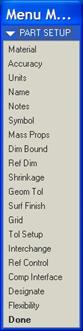
To get to some setup options for the model, go to Edit, Setup from the menu bar. You will get the following menu.
Units
When you select Units you will get the following window.
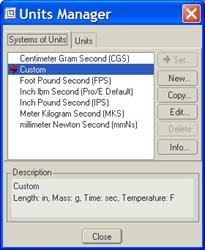
The red arrow and highlighted row show you what unit is currently set. We would pick on the units that we wanted to change it to, and then click on Set. This brings up another window, which is shown at the top of the next page.
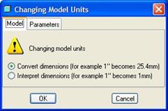
You have two options, which are:
· Convert Dimensions – This will keep the overall size of the geometry the same, and do a straight conversion on the numbers. For example, suppose you had a cube that was 1.0 inches in size. If you use this option, the cube will still be 1.0 inch in size, but if you were to edit the feature, you would see 25.4 if you switched to millimeters.
· Interpret Dimensions – This does the reverse. This keeps the dimension value the same, and turns it into a different unit. In the same example, the 1 inch cube would become a 1 millimeter cube with this option, since the value of 1.0 stayed the same.
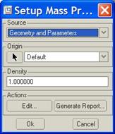
Density (Mass Property)
To set the density for the part, pick on the Mass Props menu choice. It brings up the following window.
FEATURE OPERATIONS (Copy, Group, etc.)
When you select Edit, Feature Operations you get the following menu.
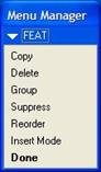
Copy
Use this command to copy any solid feature by either translation, rotation or mirroring about a selected plane. This is the only way to mirror a solid feature. To mirror, click on this command, then pick the feature(s) to be copied. You will get the choice to make the copy dependent on the original for size and shape, or make it independent so you can modify it separately. Once you have picked the feature(s), click on Done, then pick the mirroring plane or planar surface. The feature will be mirrored.
Group
When you click on this command, you will get a File Open window to go out and try to retrieve a user defined group. In the menus, you will select Local Group, and then enter a name for the group in the message window.
After you enter a name for the group, pick on the features in the model tree that are going to be grouped together. The features should be modeled sequentially. To ungroup, right mouse click on the group in the model tree and select Ungroup.
Reorder
You can and should reorder in the model tree by dragging the feature up or down to its new place. If you have a lot of features, you can save some dragging time by going straight to this command. When you use this command, it asks for the feature(s) to reorder, then it asks you to select the feature that you wish to reorder after. Assuming that there are no problems with parent/child relationships, it will reorder then regenerate the model.
Insert Mode
You can and should drag the red arrow that says “Insert Here” in the model tree to the location where you want to insert a new feature. If you have a lot of features, you can save some time by using the command here. After you select this command, click on Activate. You will be asked to pick on the feature to insert after. To cancel out of insert mode, click on Cancel. This will regenerate all the features that were currently suppressed, and take you back to the end of the model tree.
Read-Only
Be careful using this. When you click on this command, you will pick a feature in the model tree. All features before the selected one become read-only. You can’t edit a dimension or redefine the features if they are read-only. You will need to use Clean in the Read-only menu to clear this status.
Suppress
Suppress is used to turn off features from the regeneration sequence. They disappear from the model. You should only use suppress in the following cases:
· Family table features. Use suppress in the generic and instances to turn of features that are not in that instance.
· Failure recovery. Temporarily suppress failing features so you can go in and fix them or other features one at a time.
· Design Iterations. Temporarily suppress a feature to try a different possibility. Delete the ones you end up not using.
Other than in family tables, there should never be any suppressed features in your model when you go to release it.
COLOR AND APPEARANCE
Adding color to your models is a great way to visualize them. To add colors, go to View, Color and Appearance from the menu bar. It will open up the window shown in the next figure.
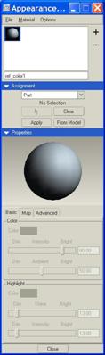
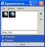
If you have a saved color file, then you can load it in, or it may already be loaded. We can see from this figure above that there are no pre-defined colors in this session. To add a new color, click on the “+” symbol at the top.
A name appears in the bottom field of this portion of the window. You can and should edit the name to something meaningful, as shown below for a bright red color that we are adding.
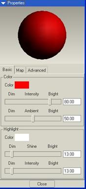
Once you add the new color, go to the Properties portion of this window, click on the Color swatch and define your color, as shown in the next figure.
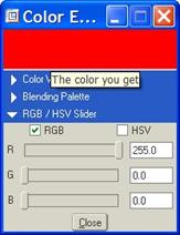
When you click on Close you will want to change other settings, such as brightness, transparency, etc. These choices are in the tabs at the bottom of the window, as we can see below.
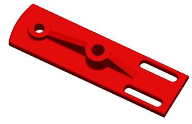
When you are ready to assign the color, go to the Assignment portion of the window. Use the pull-down to select the scope. By default, Part is chosen. This means that we will assign the selected color to the whole part. You can also choose surfaces, components (in assembly mode), etc.
The following figure shows the assignment of this color to one of the parts we have been working with in the past lessons.
PARENT/CHILD RELATIONSHIPS
Because Pro/ENGINEER is a feature-based modeling tool, we are bound to have features that rely on other features to exist. Every time we pick a surface as a reference, or an edge, or a plane, etc. we are creating these dependencies.
These dependencies are classified as either parents or children. For example, suppose we create an extruded protrusion. Then we round an edge on that protrusion. The protrusion is the parent, and the round is the child. You can delete the round and the protrusion won’t care. But, if you try to delete the protrusion, the round will be directly affected.
To view existing parent-child relationships for any given feature, select that feature, and then right-mouse click on it and go to Info, Parent/Child. You get a window that looks like the following.
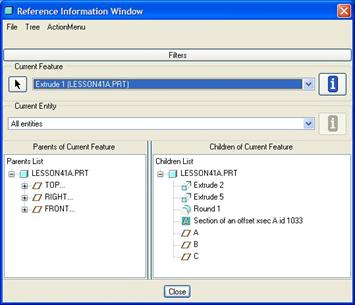
At the top, it shows the feature that we are running the report on. In the bottom left, we get a list of all of the parents of this selected feature. On the right, we get a list of all of the children of this feature.
Can you reduce parent child relationships in your model? Sure you can. The easiest way to reduce the number of relationships is to try to use the default datum planes as much as possible for sketching planes, sketching references, and dimensional references. But, the moment you use a Use Edge or Offset Edge or select a vertex or edge or surface as a reference in the sketch, you have created that parent/child relationship. It is unavoidable.
My advice is to never delete or suppress a feature until you have run this query. Then, at least, you will be prepared to see things disappear.
MODEL PLAYER
Whenever you get a model to work on that you didn’t create, you should immediately use the model player, found under Tools, Model Player in the menu bar. This will bring up the following window.
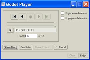
You will use the arrows at the top to step through the model from start to finish. As you pick on the “Next” arrow, the feature that is displayed will appear in the working window. You can pick on the Show Dims button at any time to see the dimensions used for that feature (if any).
COSMETIC SKETCHES
A cosmetic sketch is used to convey information on the part without creating a solid or datum feature to do it. A great example is a logo or part marking. There are a few restrictions when using them.
The first is that the cosmetic sketch can not cross over surface boundaries if projected. The other is that you can not hatch a projected cosmetic sketch.
Cosmetic sketches are either sketched directly on a surface similar to a sketch feature, or they are projected onto a single surface, similar to a projected datum curve.
The following figure shows a cosmetic sketch for our logo on a part.
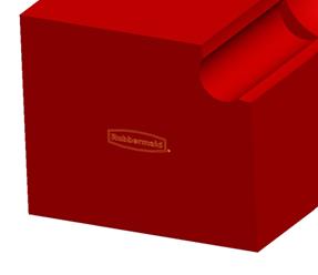
Cosmetic sketches are accessed through Insert, Cosmetic, Sketch in the menu bar.
ANALYSES
There are a lot of different analysis tools in Pro/ENGINEER. We went through a draft check analysis back in Lesson 15, and we saw the results of a Gaussian Curvature analysis in Lesson 22.
There are three additional analysis that are used widely.
Mass Property Calculation
Use Analysis, Model Analysis then select Model Mass Properties from the pull-down. This gives us the following window.
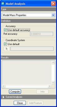
Most of the time, you can just hit the Compute button. The analysis results include (but are not limited to): Mass, Volume, Density, Center of Gravity, Total Surface Area, Moments of Inertia, etc.
We need to run this analysis before our mass parameter will show the correct value in the drawing title block.
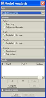
Global Interference Check
In an assembly, you can run this analysis to check for interference between parts. Go to Analysis, Model Analysis, then select Global Interference from the pull-down. It will look like the following.
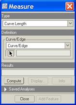
Measure
Use this to take measurements between surfaces, planes, points, vertices, axes, or other entities. This is found under Analysis, Measure. It brings up the following window.
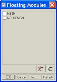
FLOATING MODULES
To access any floating modules, go to Tools, Floating Modules. Floating modules are applications that we have with the software, but they are not tied to any particular license. They float on the network, and can be accesses on a first-come-first-serve basis. Two are shown in the window that pops up.
LESSON SUMMARY
This Lesson marks the end of this training guide. Be sure to keep this guide handy. If you have any Pro/ENGINEER questions, contact your CAD Administrator or PTC through one of the following methods.
PTC Phone Support: 1-800-477-6435
PTC Online Support: www.ptc.com – select on the support link at the top.
EXERCISES
None