Lesson 47

Lesson Objective: In this lesson, we will learn how to show and create dimensions in our drawing.
SHOW VS. CREATE – THE GREAT DEBATE
One of the biggest debates in the Pro/ENGINEER community is the question of whether you should show dimensions that are in the model, and design accordingly, or whether you will just simply create dimensions in the drawing.
The reality is that it depends on several things:
1. Product Definition – If we are talking about fixtures, sheet metal parts, or parts that have predominantly linear or cylindrical surface definitions, then I personally feel that users should show more dimensions than create. For products that are defined with many swoopy 3D curves and surfaces, the availability of well-defined dimensional constraints in the model is less, so showing dimensions may not present a realistic solution to creating drawings.
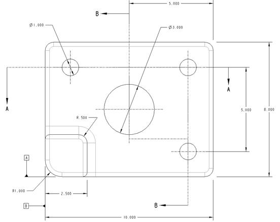
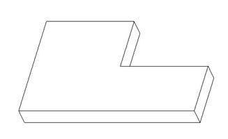
2. Fit, Form and Function versus Manufacturability – The other driving factor is whether it is possible to capture manufacturing dimensions in the model and preserve design intent. This is, perhaps, one of the biggest cases made for creating dimensions. For an example, we will look at the following bracket design:

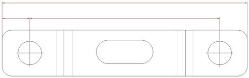
Suppose that the bracket in the previous figure must be designed so that it always mounts perfectly depending on the spacing of the two posts. Another requirement might be that the outside of the bracket must line up perfectly with the outside edges of the posts.
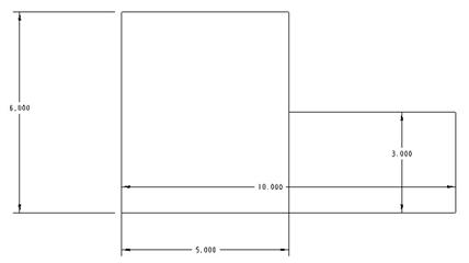
Therefore, the direct spacing between the holes is critical for satisfying the first condition, but the overall width of the bracket can not be specified and still maintain design intent for the second condition. Instead, the dimensioning scheme for the model might have to be created as follows.

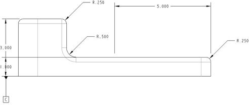
From the previous figure, we can see that the dimension between the two holes is defined, and the distance from the hole to the outside of the bracket on each side is defined. This scheme will allow us to take the width of the posts, as well as the spacing of the posts into consideration for our bracket design.
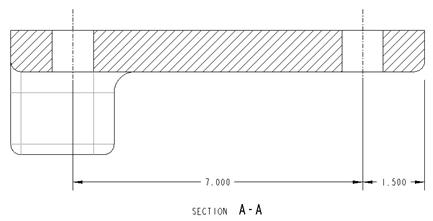
Unfortunately, we can not manufacture the bracket this way, because we would first start with the metal and bend it to form the main geometry of the bracket, and then put the holes in afterwards. Therefore, on the drawing, we might have a different dimensioning scheme, as indicated in the next figure.
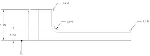
Another possible manufacturing scheme might be…

As you can see, both of these schemes allow for the creation of the bracket geometry first, and then the holes second. Unfortunately, all three modes potentially create a different result based on dimensional tolerances.
The good news, you can combine both schemes into the drawing, by showing the fit, form and function dimensions, and then specify the overall length as a reference, or a “Basic” dimension, and then specify the three shown dimensions as critical or “inspection” dimensions, as shown in the next figure.

In this lesson, we will see how to do both – show dimensions in the drawing that were created in the model definition, and how to create dimensions directly on the drawing.
SHOW DIMENSIONS
To demonstrate this functionality, we will open up the drawing called Show_Draw.drw. It currently contains four views, as shown in the following figure.
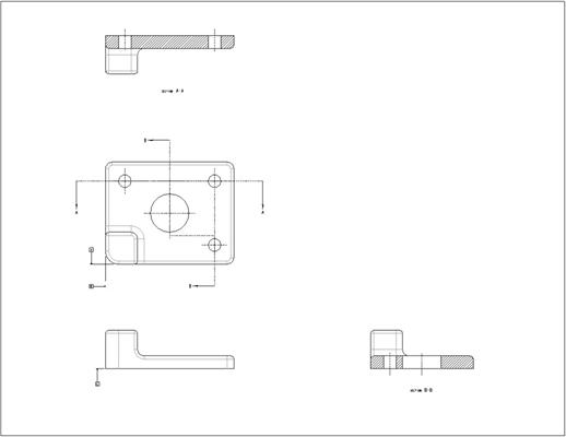
Our first general view creates the front view in the lower left corner. We then added a projected view off of this towards the top to create our next view. From that TOP view, we projected another view, and made it a section view (Section A).
From the first general view, we projected a RIGHT view, and used an offset cross-section for this view (Section B). On the views, you can see axes where appropriate, and you can also see three set datums for this part (A, B, and C – on the FRONT and TOP views).
We are now going to show the dimensions for this part. Therefore, we will go to our Show/Erase tool in our drawing toolbar (the one that looks like a flashlight), or go to Edit, Show and Erase from our menu bar. We get the familiar show and erase window. We want to make sure that the Show button is pressed in, and that the first dimension button is pressed in. All other buttons should be depressed, as shown in the next figure.

For this example, we will click on the Show All button (since we don’t have that many dimensions on our model). We get the confirmation window, as shown below.

Click on Yes to confirm showing all of the dimensions in the model. When we do this, dimensions show up on the drawing views where they are able to be shown, and we will pick on the Accept All button in our Show/Erase window. When we do this, all of our dimensions are currently highlighted in red, as shown in the next figure.

It keeps the dimensions highlighted until you click on the refresh button. We will zoom in on the TOP view first to clean up the dimensions.
CLEANUP DIMENSIONS
If we zoom in on the TOP view, we can see the following.

We only have seven dimensions on this view so far, so dragging each one to clean up the view isn’t really that big a deal, however, we will take a moment to show the cleanup tool.
First, click anywhere on the drawing (away from any entity), and the dimensions will de-select. We can use the clean-up tool to clean up all dimensions on the drawing, but we will just focus on this view right now.
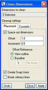
Once all of the dimensions are no longer selected, drag a box around this view (make sure it is big enough to go around all of the dimensions. Do not worry if it gets a dashed border around the view as well. Once you have all of the dimensions highlighted for this view, go to Edit, Cleanup, Dimensions, from the menu bar, which brings up the following window.
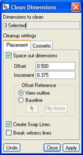
We will take a moment to talk about this window, and what it does. First of all, we notice at the top that it says 3 Selected. If you remember, we have 7 dimensions on this view, so why is it only reporting 3? Only linear dimensions are affected in the cleanup process. Diameter/Radius dimensions are not included. If we look at the view, we can see that we have only 3 linear dimensions (the width of the block (10”), the height of the block (8”), and the width of the protrusion on top of the block (2.5”)).
The next thing we see are two tabs. The first tab, which is currently selected is Placement. The first thing we can define in this tab is how it spaces out the linear dimensions. If you notice, we have only one linear dimension on the right side of this view, but we have two dimensions on the bottom of this view.
When we space out the dimensions, one of the dimensions will start out a distance away from the view specified by the Offset value. In this case, our first dimensions will be spaced 0.5” away from the view.
The next dimension, and the one after that, and so on will be spaced according to the Increment value. On the right side of the view, we only have the one dimension, so it will sit out 0.5” from the view. On the bottom side of the view, we have two dimensions, so one of them will sit out 0.5” from the view, and the second will sit out 0.375” from the first one.
So, what determines the starting point for the offset value of 0.5”? Currently, the Offset Reference is specified as the View Outline. In other words, when you pick on a view, and you see a dashed rectangular border around the view, that is the view outline. Therefore, the first dimension will be offset 0.5” from the dashed rectangle. If you want to use a different reference, such as an edge of the model, you can select the Baseline option, and choose the reference. We will keep it as the “View Outline”.
Finally, we have the option to create snap lines and to break witness lines. A Snap Line is a dashed, muted line that only appears electronically on the drawing, and is used to allow you to snap dimensions to it. If we were going to show more dimensions later, we could snap the newly shown dimensions to the existing snap lines. If we select this option, we will get snap lines at 0.5” from the border, and 0.375” from the first snap lines for any additional dimensions that we have. We will leave this option selected right now.
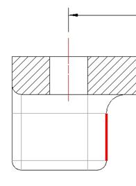
By default, we don’t have the Break Witness Lines option selected. A “Witness Line” is the leader line that goes from the dimension back to the geometry. If you have lines that overlap in the drawing, you can have one of the lines broken so there is a small gap, as shown in the next figure.
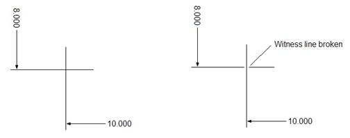
The figure on the left above shows overlapping witness lines without a break, while the figure on the right shows the witness line for the 8.0” dimension broken to make it easier to see the lines. This is a cosmetic feature, but I recommend it.
Now, in our drawing, none of the linear dimensions will overlap witness lines, so we really don’t have to worry about checking this option. For now, we will change the two offset values as follows: Offset = 1.0, Increment = 0.5. The Placement tab should now look like the following.
Now, we will click on the Cosmetic tab, which looks like the following figure.
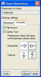
On this tab, we have some additional ways to control the look of the dimensions and arrows. If the witness lines are too close together, the system can automatically flip arrows to the outside of the lines. We can also center our text on our lines. We will leave both of these options selected.
Down in the lower part of this tab, we can see how to adjust our text if we have to place it outside of the witness lines. We will leave the default options of placing the text to the left and/or top (depending on the orientation of the dimension).
We will now click on Apply to see how these settings affect our view. We see the following.

We can see that our linear dimensions have moved to the outside of our drawing view. We can also see that there are three dashed snap lines. One is really obvious – the one that the 2.5” dimension sits on. The others are harder to see, because the dimensions and leader lines are sitting right on top of them.
For this drawing view, we really didn’t have to use the cleanup tool for only three dimensions, but it was a good exercise to learn how to do it, because, if you have a model with a lot of features, and you decide to use the “Show All” option, you can perform an initial clean-up that will make it easier to come back and perform your manual clean-up later.
If we didn’t like the way the clean-up looked, we could click on the Undo button, and reset our values, and re-apply the clean-up. We will click on Close to accept this clean-up. Click outside of the view to de-select all dimensions.
MANUAL CLEANUP
Staying on this view, we will perform some manual clean-up. Just as we did with axes and GTOL datums, we can drag dimensions around to where we want them. If we pick on one of the squares at the end of leaders or witness lines, we can control the length of the lines, and the distance of the text.
We will drag our dimensions around so we are left with the following.

Since we moved our dimensions off the snap line, we probably don’t need them anymore. Therefore, click on a snap line, and then hit your <DELETE> key on your keyboard. Click outside the view to refresh it.
HINT: As you drag a dimension, if you click on the right mouse button, it flips the arrows on-the-fly.
Now, we will go to the FRONT view. It currently looks like the following.
Okay, we can see that this view has several things that need to be fixed. All of the linear dimensions across the top describe holes in the model. The problem is that we can not see the holes on this view.
NOTE: Even if you were to turn on hidden line display for this view, it is against ASME Y14 standards to dimension to hidden entities. We will have to move these dimensions to a view where we can clearly see the holes.
MOVE ITEM TO VIEW
To move a dimension from one view to another, we first select the dimension to move. In this case, select the 7.000, and 1.500 linear dimensions at the top of this view using the Ctrl key to get both of them. Be sure not to select the 0.250” radius dimension, or the 5.000” linear dimension.
Once these dimensions are selected, hold down the right mouse button over one of the selected dimensions, and select Move Item to View. (You can also access this through Edit, Move Item to View from the menu bar). We must now select the view we want to move them to. We will select on the Section A-A view (at the top of our drawing). When we do this, the dimensions leave the FRONT view, and jump to our section view, as shown in the next two figures.
FRONT VIEW
ALIGN DIMENSIONS
When you have two linear dimensions that are next to each other, as we do in our section view, we can line them up on the same horizontal or vertical without having to use snap lines. In our Section view, we want to move these dimensions above the view, so the witness line for the 7.000” dimension doesn’t cut through the view, overlapping the geometry.
Therefore, we will select both of these dimensions using the Ctrl key, and then right click on one of them and pick Align Dimensions. When we start dragging, we can see that both dimensions move at the same time. We will drop the dimensions as shown in the next figure.

Notice that when we do this, our witness lines are still embedded in the drawing. One thing to point out is that when you print out this drawing, the witness lines will clip back to the ends, but from an electronic viewing, this is still messy. I personally like to keep my drawings clean on the screen as well. Therefore, we will drag our witness lines to clean them up as shown in the next figure.

Return to the FRONT view, and we will clean up the dimensions as shown in the next figure.

Again, we will have to move one more dimension. The 5.000 dimension goes to the center of the large hole. We will need to move this dimension to our TOP view. Therefore, click on this dimension, hold down the right mouse button and select Move Item to View, and then pick on the TOP view. Clean up this dimension as shown in the next figure.

This was the only view that would accommodate this dimension, because it is the only view that has the center of the large hole visible, and where we can see the right edge of the model where the dimensions goes to.
Finally, we will go to the Section B-B view to clean it up. It currently looks like the following.

We can keep two of these linear dimensions, but we will need to move the 5.000 dimension to the TOP view. This view, when cleaned up will look like the following.

Clean up the TOP view once more for this newly moved dimension. NOTE: You may need to move the section view arrows for A-A to get it clean, as shown in the next figure.

FLIP ARROWS
On two of our view, we may wish to flip the arrows of some of the dimensions to clean it up a bit. Go to the FRONT view. As you can see, we have a linear dimension on the left side for the height of the plate. We are going to demonstrate how to flip arrows and we want to move the dimension over to the right side of the view, where it makes more sense to show it.
Just Flipping the Arrows
If you don’t want to move the dimension, just flip the arrows, you select the dimension first, and then hold the right mouse button down and select Flip Arrows. We will do this first for the 1.0 dimension. When we do this, our view looks like the following.
Flipping Arrows While Moving
Now, we will click on the dimension to move it to the right side. As you are dragging the dimension, try clicking with the right mouse button. What happened? The arrows went back to the inside of the witness lines. Click once more with the right mouse button (while still dragging), and you will see the arrows flip back to the outside. Place the dimension and clean-up as shown below.

This works just as well for radius and diameter dimensions, as well as angular dimensions. At this point in time, our dimensions are all placed, as shown in the next figure.

Save this drawing. We will continue to work with it in the next section.
EDIT MODEL THROUGH DRAWING
One of the advantages of shown dimensions is the ability to make design changes from within the drawing. Created dimensions are read-only, but shown dimensions are fully associative and parametric with the model, since they came directly from the model definition.
To demonstrate this, go to the TOP view in our drawing. It currently looks like the following.
We want to change the large hole diameter from 3.000 to 2.000. Therefore, click once on the 3.000 diameter dimension to select it, and then double-click on the “3.000” text. (We will explain in a minute why we did this in a two-step select process). When we do this, an edit field appears on the dimension, as shown in the next figure.

Change the value to 2.0, and then hit the enter key. Now, using Edit, Regenerate, Model or click on the following icon in the system toolbar:
![]()
The model will regenerate, and the drawing view will update to show the new geometry and dimension value, as shown in the next figure.

If we look at our Section B-B view, we can see that the cross-section has updated as well.

If we open up the model, we can see that (as expected) the hole is at the smaller diameter.

This is a two-way associativity. If we make a dimensional change in the model, it updates the drawing as well. In the case of created dimensions, the dimensions will update, but you can not drive the model from the drawing with created dimensions.
Save the model and close it. Save the drawing, but leave it open for the next section.
CREATE DIMENSIONS
As we talked about in the beginning of this lesson, there are many times when you may need to create a dimension in your drawing instead of showing one. My absolute advice is the following:
1. Rule 1 – If you have the dimension already in the model, always show it.
2. Rule 2 – If the dimension is going to be an inspection dimension (critical), it should probably be in your model to drive changes to the model, and to perform any necessary analysis on the dimension as you are designing. Critical dimensions should typically be shown dimensions (not always, but I make it a habit of trying to do it as much as possible).
3. Rule 3 – If you need to dimension to geometry within a cross-section, you might want to create a cross-section datum curve first so you have well-defined entities (edges, vertices, etc.) to select from when dimensioning. Often it is difficult in drawing mode to select the entity you want. You can then hide the curves in layers when done.
4. Rule 4 – Avoid creating draft geometry to facilitate dimensioning. In a later lesson, we will learn all about draft geometry. For now, suffice it to say that it is easier to create the geometry as curves in the model and then reference these entities in the drawing. You can always hide this geometry in layers when you are done.
I can not stress the importance of following these rules. If you don’t you may find yourself frustrated with using the tool the way it was not intended to be used.
Having said all that, we will get into learning how to create dimensions. To demonstrate this functionality, we will return to our drawing that we’ve been working with in this lesson. Go to the Section A-A view. We are going to create couple of dimensions for this view just to show how it is done. NOTE: You want to avoid an over-dimensioned drawing. Because all of our current dimensions are shown, and we are showing every one from the model, any ones that we add as standard dimensions now will over constrain the drawing, and could confuse manufacturers – especially if we specify conflicting tolerances. So, we will put aside common sense for the purpose of this exercise.
Standard Created Dimensions
We will start by adding a radius dimension to the round at the right side of this section view. Therefore, we will go to the create dimension tool on our drawing toolbar, or go to Insert, Dimension, New Reference.
Pick once on the arc shown in the next figure.

When we do, it highlights in a bold red, as shown in the next figure.

Now, click with the middle mouse button where you want the dimension to be, and you will get the following.

Try to change this dimension value here in the drawing. What happens? Down in the message bar, we get the following error:
![]()
Now, we will add a linear dimension from the axis of the left hole to the right edge of the protrusion sticking out of the plate. Therefore, click on the create dimension tool again, and this time start by picking on the axis. It will highlight in red. Next select the right edge, and it will highlight in a bold red, as shown in the next figure.
Now, using the middle mouse button, pick outside of the geometry below, and in between the two selected references to place the dimension as shown.

We can clean up created dimensions the same way we clean up shown dimensions. Therefore, flip the arrows to get the following.

Save the drawing.
CREATED REFERENCE DIMENSIONS
Whenever you need to add a dimension that is not critical, but may potentially over constrain the drawing, you should use a reference dimension. Tolerance is not applied to reference dimensions, so be careful which dimensions you choose to consider “for reference only”.
To create a reference dimension, you would select Insert, Reference Dimension, New Reference, and then select the references as you would with the creation of any type of dimension. We will create a reference dimension for the distance from the left edge of the section view to the left hole axis, as shown in the next figure.

We can see the parenthesis placed around this newly created reference dimension. We will flip the arrows and align this dimension to the other two linear dimensions to clean it up as we can see in the figure above.
As a typical rule, reference dimensions are the most commonly “created” dimensions in drawing mode. You can, however, create reference dimensions in the part and show them in drawing mode – the choice is up to you. I personally find it easier to create reference dimensions in the drawing.
Save the drawing and close it. We will come back to it in a later section of this lesson.
ORDINATE DIMENSIONING
If you recall from Lesson 4 – Sketcher Basics, we learned how to create ordinate dimensions when sketching a feature (Pg 4-22). Sometimes, you don’t have the luxury of having the forethought to use ordinate dimensioning from the start. Once you get to the drawing, you might think it is too late to show ordinate dimensioning, but it isn’t.
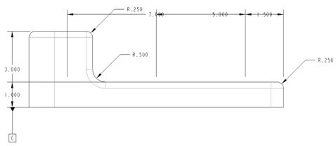
In this section, we will learn how to convert a set of linear dimensions to ordinate dimensions. To do this, we will open up a drawing called Ordinate.drw, which currently looks like the following.
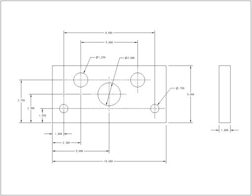
Okay, let us first take a look at this drawing and point out a couple things. The first is that any radius or diameter dimension can not be converted to an ordinate dimension.
The second thing we notice is that in the horizontal direction, we have two linear dimensions that represent the distance between similar holes (8.000 and 5.000 dimensions at the top of the FRONT view).
In order to convert dimensions from linear to ordinate, the witness lines for the dimensions must share the same reference. For example, all of the linear dimensions at the bottom of the FRONT view all reference the left edge of the model. Therefore, all of these can be converted to ordinate dimensions using the same baseline (where the dim is 0.0). The two hole spacing dimensions at the top of the view do not share a common reference with each other or with the linear dimensions at the bottom. Therefore, we will either leave these as linear dimensions in this drawing, or go back and edit the sketch for these features and change the dimensioning scheme.
NOTE: Remember your design intent. If the fit, form or function of this drawing requires the distance between the holes to be maintained, then you should leave them as linear dimensions in the drawing.
For the vertical dimensions, all of them reference the bottom edge of the model, so all of these can be turned into ordinate dimensions.
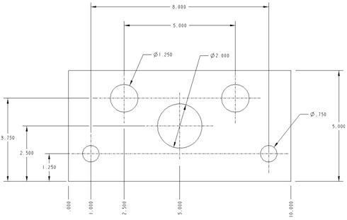
We will now demonstrate how to do this conversion. First, start by selecting all of the linear dimensions at the bottom of the FRONT view, as shown in the next figure.

With these four dimensions highlighted, go to Edit, Toggle Ordinate/Linear. When we do this, we see the following.

We have a “.000” baseline at the left of our model, and all the other dimensions for the holes and the plate are in ordinate dimensions. We can use the Align Dimensions command to clean them up as shown.
Now, select the three linear dimensions on the left side of the view, and the one on the right side of the view using the Ctrl key, as shown in the next figure.

Once all four dimensions are selected, use Edit, Toggle Ordinate/Linear once more. We will get the following ordinate dimensions.
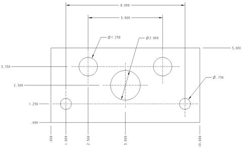
Align the dimensions, and clean up the view as shown in the next figure.

Save and close the drawing.
BACK IN THE MODEL
So, what effect did converting the dimensions do to the model? If we open up the Ordinate.prt model, and edit the second extrude feature. We will see the following.

As you can see, the dimensions are now in ordinate form in the part as well. Remember, these were associative, shown dimensions, so they updated automatically. So, this begs the question, can you do this with Created Dimensions?
The answer is yes. As long as your created dimensions are going to the same reference (in this case the left edge of the model), we can toggle them to ordinate as well.
Close this part.
SKETCHER TO DRAWING
When you are showing dimensions on a drawing, the approximate placement of the dimension will be as it was when you sketched the feature that created that dimension. So what does this mean? If you get in the habit of cleaning up your sketches as you make features, you will have a lot less clean-up to do in drawing mode.
To demonstrate this, we will go through an example. Create a brand new part called Sloppy. Create an extrude feature using the TOP datum plane as the sketching plane, and face the RIGHT datum plane towards the right.
Create the following sketch (be sure all dimensions are strong and located exactly where you see them in the next figure).

Now, extrude this to a depth of 1.0 to create our model, as shown in the next figure.
Now, we will go and create a new drawing called Sloppy, and use a C size sheet, as shown I the next figure.

Create a general view and use the TOP saved view to orient it. Next, go to the Show/Erase tool and show all dimensions. This is what you will get when you Accept All.
Notice how the dimensions came in exactly as they were in the sketch? Think this is a coincidence? Go ahead and close out of this drawing and close the part, and create a brand new part called Clean. Create an extrude using the exact shape and size as before, but clean up the dimensions in the sketch to look like the following.

Extrude to 1.0 to complete this model, and then create a new drawing called Clean. Use the same sheet size of C, and make sure that the model is the Clean.prt file that we just created. Add a General view, and use the TOP orientation as before.
Show all dimensions, and accept all that show up. Notice a difference?

As we can clearly see, the time spent cleaning up our sketch is well worth it if we know we are going to show dimensions in our drawing. I would get in the habit of cleaning up your sketches anyway, because someone may inherit your model later, and it will be easier to figure out what you were doing with a clean sketch (remember, don’t leave any weak dimensions either).
Close these models without saving.
DIMENSION PROPERTIES
When you show or create a dimension on your drawing, it takes on the characteristics of the drawing setup file in terms of text height, text spacing, arrow size, arrow length, etc. There are a lot more things we can do with dimensional properties within the drawing itself. To demonstrate this, go back to the Show_Draw.drw drawing that we started with in this lesson. It should currently look like the following.

We will go into the FRONT view in the lower left corner, which currently looks like the following.

Do you remember when we changed the dimension of the model directly in the drawing? Do you remember how we clicked once to select the dimension, and then double-clicked to edit the dimension?
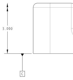
Well, if we were to simply double-click on a dimension (shown or created), it brings up the properties of that dimension. For example, double-click on the 3.000 height dimension on the left side (be sure that it was not previously selected). When we do this, we see the following.
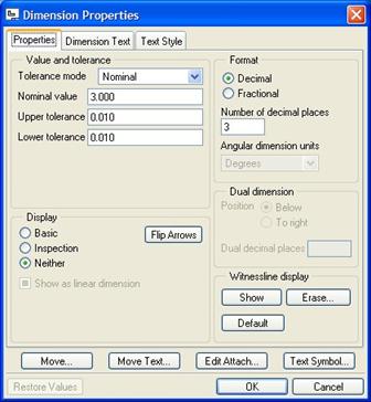
The Dimension Properties window contains three tabs: Properties, Dimension Text and Text Style. We will focus on each one independently.
PROPERTIES TAB
The properties tab is used to specify the format of the dimension. It includes the ability to set dimensional tolerances, change the fraction from a decimal format to a fractional format, specify the number of decimal places shown (which will affect rounding), control dual dimension text formatting, witness line visibility and also specify whether this dimension is a Basic or Inspection dimension.
Display
We will come back to Tolerancing in the next section. For now, we will look at the Display section, which looks like the following.

Currently, this dimension is displaying as a regular dimension. We will select on the Basic option, and then click on OK to make the change. On our drawing view, we can see the result.

Double-click on the dimension again to get back to the properties. This time, pick the Inspection option, followed by OK. We now have the following.

So, what is the difference between a Basic and an Inspection dimension?
Inspection Dimensions
Typically, all standard dimensions on a drawing (with the exception of reference dimensions) are subject to inspection for quality purposes. The practice of calling out a sub-set of dimensions that must regularly be checked after first article release has led to the creation of inspection dimensions in drawings.
In some cases, separate drawings were created for quality control that only contained specific dimensions to inspect to as the product came back from manufacturing. For companies that prefer to create a master document and reduce potential error from multiple copies floating about, it became common practice to use special symbols to represent dimensions that needed extra attention.
Today, most CAD systems include a built-in mechanism that helps identify these dimensions by applying an oblong shape around the dimension. An oblong is used because there are no other oblongs defined in ASME/ISO standards. Tolerances can be shown within the oblong.
Basic Dimensions
A basic dimension represents a numerical value used to describe the theoretically exact size, profile, orientation, or location of a feature or datum target. It is the basis from which permissible variations are established by tolerances on other dimensions, in notes, or in feature control frames.
In other words, a basic dimension is not subject to tolerances, is not necessarily important enough to inspect in every time, and yet is held to its value, unlike a reference dimension. Use a basic dimension, when you know this is the exact value it should be, regardless of applied tolerances.
Typically, basic dimensions are denoted by a rectangular box around the dimension, and no tolerance appears in the box.
Format
Double-click on the dimension again to get back to the properties window, and then change the display back to Neither to remove the Inspection symbol. Now, we will look at the Format section, which currently looks like the following.

Currently, our dimensions are shown in decimal format, and the number of decimal places shown is three. Change the option to Fractional, and you will see the following.
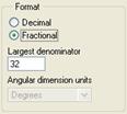
Instead of the number of decimal places, we are asked to enter the largest denominator for the fraction. In this case, it is 32. Therefore, if our dimension had been 1.500, it would have shown up as 1-1/2 (it doesn’t automatically try to make a fraction with a denominator of 32, which in this case would be 48/32).
If we click on OK you will get the following.

We can see that no decimal places are shown in fractional form (as expected). IMPORTANT: For tolerance reasons, you have to be extremely careful when using fractional dimensions. Why? Isn’t “3” the same as “3.000”? Not to a manufacturer. Suppose we have a general tolerance as follows:
x. + .5
.x + .1
.xx + .05
.xxx + .01
Now do you still think they are the same? “3” can be any number in the range of 2.5 < x < 3.5, while “3.000” can be any number in the range of 2.99 < x < 3.01. This is a huge difference if tight fits are required.
We will set the dimension back to decimal format with three decimal places.
Dual Dimension
In this drawing, we currently don’t have dual dimensioning turned on. Had we had dual dimensioning on, we would have two dimension values shown for each dimension on this drawing – one on top of the other.
The dimension on top represents the Primary Units of the drawing, while the dimension on the bottom represents the Secondary Units of the drawing. In this example, our primary dimensional units are Inches, so the secondary units would be Millimeters. The typical format for a dual dimension is as follows:
PRIMARY UNITS
[SECONDARY UNITS]
The following figure shows what this drawing view might look like if we had dual dimensioning turned on:

Okay, a few things to point out. First, the number of decimal points are going to be equal. The reason for this deals with the idea of trailing zeros. In Metric, trailing zeros are not permitted. Pro/ENGINEER knows this based on the drawing setup file. Therefore, our 3.000 dimension (which goes to 3 decimal places) equates to 76.2 millimeters (3.0 * 25.4). It is not shown as 76.200. Why is this important?
We do a lot of manufacturing oversees, where the metric system is prevalent. If we model our designs in inches, and then produce drawings with dual dimensions, there is a good chance that the manufacturer will look at the bottom number for manufacturing or inspecting. Generally, this isn’t a problem. Sure, there is some rounding going on when converting from English to Metric, but generally Pro/ENGINEER does a good job in maintaining consistency in the conversion.
The problem could arise if general tolerances are used on the drawing. Going back to our example before, we might have English tolerances as follows:
x. + .5
.x + .1
.xx + .05
.xxx + .01
From a conversion standpoint, the equivalent in metric would be:
x. + 12.7
.x + 2.54
.xx + 1.27
.xxx + .254
Okay, if we look back at our current dimension, we know that our height can vary from 2.99 to 3.01 (based on three decimal places). If the manufacturer is looking at the metric dimensions (but following the general tolerances listed on the drawing), there is a chance (possibly slight – but it still exists), that they might end up doing 76.2 + .1 (which is the metric dimension with the English tolerance for one decimal place applied). This gives us a range of 76.1 to 76.3 millimeters, which is equivalent to 2.996 to 3.004 inches.
Okay, you might be saying – wow, this would actually be better, because it is a tighter tolerance, and still leaves room for most of the English range. Aside from a potential in cost difference to hold to this tolerance, going from English to metric doesn’t seem as bad.
If we had the opposite, a metric drawing with English secondary units, and we called out general metric tolerances, the results are quite different. We won’t go through an example of this, but try it on your own.
The bottom line is that when you use dual dimensioning, you should watch out for possible rounding or misinterpretation errors that may occur.
Witnessline Display
The last section on this tab that we will talk about here is the witness line display section, which looks like the following:

Working with the same 3.000 dimension, we will click on the Erase button. We are prompted to pick one or more lines. We will pick the top witness line for this dimension, followed by the middle mouse button to complete the selection. Click on OK to close the properties window, and you will see the following.
Notice that a Double arrow appears on the end of this dimension where the witness line used to be. Typically, you see this in partial or detail views where the geometry the dimension connects to on one side is not in the current view.
The recommend practice for this is to set up a set datum on the reference that is not visible, and then call out the datum in the dimension, as shown in the next figure (assuming Datum “D” is the datum that is not on this view)

This can be done in the second tab of our Dimension Properties window, which is coming up soon in this lesson. For now, we will double-click on the dimension once more, and click on Show back in the Witnessline Display section to get back the witness line that we erased.
DIMENSION TEXT TAB
The next tab in our properties window is the Dimension Text tab, which looks like the following for our current dimension:

In the main field, we can see a value of @D. This is telling how to display the dimension value. There are three options that can follow the “@” symbol. These are:
· @D – Shows the actual dimension value on the drawing. This is the default for dimensions.
· @S – Shows the symbolic name for the dimension on the drawing. For example, you can see in this figure that our dimension’s symbolic name is currently d5, so if we edit this large field and type in “@S”, our drawing would show the following:

This is especially useful for tabulated drawings where you might want to call out the length dimension on a part, and then have a table that defines what “Length” actually is for the different parts. A family table drawing is a good example where using the symbolic name instead is common.
· @O – Can only be used for created dimensions. This overrides the value of the dimension, allowing you to enter any value in. I highly recommend against using this. An example where you might use this is in a part that you only want to model part of it, like a din rail that might be 10 feet long. Perhaps you only want to model 1 foot, because all of the detail along the rail is the same from one end to the next, so you only need to call out a portion of it.
In this case, we can enter “10” for the value, and on the drawing it will appear as 10. Changing the actual dimension in the model will not update the drawing. That is why it is better not to use it. For this same example, it would be better to use a Broken view instead. We will see how to create partial and broken views in an upcoming lesson.
Remember our Section A-A view has two created standard dimensions. We could take the one at the bottom of the view and change its text to read: “@O 1396500.4” (without the parenthesis). This would result in the following on our drawing.

Clearly, this is not correct, and could never possibly be this way, but we have the ability to do this with created dimensions. This is just one more reason not to use created dimensions over shown dimensions (which don’t let you override them).
Now, within this large field, we can add any additional text we want to the existing dimension. For example, we can edit the height dimension again, and add the following:

This, combined with erasing the top witness line is what was able to give us the following:

Down at the bottom of our Display Properties window, we have a button called Text Symbol, which, if clicked, brings up the following window.

This Text Symbol window has many commonly used drafting symbols used in dimensional notes. For example, if our small holes were only 0.25” deep, instead of calling out the depth dimension on another view, we could update the dimension text with the depth symbol, followed by the symbolic name of the depth (&d31, for example), which might give us the following.

In our current tab, we also have three fields at the bottom. These fields are:
· Name – the symbolic name for the dimension (d5 in an earlier example). We can rename the dimension in this location (“Height” for example).
· Prefix – Specify a prefix in front of the current dimension (3X for example).
· Postfix – Specify text at the end of our current dimension (TYP, for example).
You can add prefix and postfix text in the large window as well, as we saw.
TEXT STYLE TAB
The last tab in our Dimension Properties window is used to modify the style of the text, including font, text size, text angle, text color, etc. This tab looks like the following.

Copy From
At the top of this window is a section that allows us to re-use any style libraries that might be set up, or to pick another dimension/note on the drawing to copy its current style.
Character
The next section down allows us to specify the font we are using. Any true-type font can be used. If you don’t have a font in your pull-down list that you need, contact your system administrator for help on getting that text into your list.
In addition to the font, you can specify the height, thickness, width factor, and slant angle for the text. Most of these use the values set by the drawing setup file. I would not override these unless you absolutely had to, as these are based on current standards.
If you need to underline your text, you can click on the check box entitled Underline.
Note/Dimension
In the final section, we can specify some effects for the text, such as the justification (center, left, right), the alignment (vertical/horizontal), the color of the text, line spacing for multi-line dimensions or notes, whether the text is mirrored, and margins for text inside table cells. Again, I would keep the default settings for most of these, as they are driven by the setup file. Justification is the only one that is often changed.
BUTTONS
At the bottom of the Display Properties window, we see a row of buttons. They do the following:
· Move – pick a new location on the screen where you want the text to be, and the dimension or note will jump to that location.
· Move Text – Keeps the witness lines and leaders stationary, and just allows you to pick where you want the text to be. This is good if you want to move a radius or diameter dimension text without moving the leader.
· Edit Attach – Allows you to specify alternate attachments for the note/dimension. For dimensions with leaders (such as radius or diameter dimensions), this is more common. For linear dimensions, you really can’t change the location where the witness lines are going.
For example, you might have a round feature in the model that goes along many edges. By default, the first edge you select in the round feature is the one that shows the dimension in the drawing. By using the Edit Attach button, you could select a different arc on your drawing that is tied to the same round feature.
Close out of this properties window, and save the drawing.
DIMENSIONAL TOLERANCES
The last topic for this lesson is how to apply dimensional tolerances. If you double-click on a dimension to get the properties window back, you can see a section on the first tab for tolerance specification.
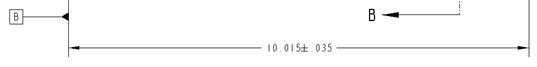
To demonstrate this, we will go to our TOP view in the same drawing, and double-click on the overall length dimension (10.000”) to bring up the properties window. The following figure shows the tolerance section of the Display Properties window.

Currently, our dimension is at its Nominal value – meaning that there is no tolerance shown for this dimension. The Nominal Value is 10.000 (which is what the dimension was set to). If we wanted to change the value of the dimension, we could do it here. The upper tolerance is currently set at 0.010, meaning that our dimension can go up to 10.010. The lower tolerance is set at 0.010 as well, meaning that our dimension can start at 9.990. We will change them to the following for demonstration purposes:
Upper Tolerance: 0.05
Lower Tolerance: 0.02
Our window should look like the following:

Using the pull-down field, we can see the following tolerance modes available to select from:

The following figures show us what our dimension would look like with the different tolerance settings:

LIMITS

PLUS-MINUS
+- SYMMETRIC
Okay, you might have noticed something a little strange. First, on the Limits setting, it used the “nominal value” + “Upper Tolerance” to arrive at the top number (10.000 + 0.050 = 10.050). For the lower number, it used the “nominal value” – “Lower Tolerance” (10.000 – 0.020 = 9.980).
This isn’t strange, it is exactly what we expected. When we picked on the Plus-Minus setting, however, our nominal value changed to 10.015 instead of 10.000. Why? It took the average of the previous result (10.000 + 9.980)/2, which gave us 10.015. Then, it divided the tolerance difference (0.05 + 0.02)/2, which gave us 0.035.
Had we picked this tolerance mode first, we would have gotten the following result.

This is what we expected to see, so why didn’t it do this? Unlike AutoCAD or other 2D drafting packages, Pro/ENGINEER is a fully parametric solid modeling tool. It gives us the ability to set our dimensions to different ranges of tolerances to check stack-up, so when we change the tolerance mode for a dimension in the model, it actually updates the model with these values. It was not simply a text edit on the drawing, it was an update to the 3D data.
Just keep this in mind if you decide to go from one tolerance mode to another, you will want to verify your numbers are correct.
Now, with the Symmetric setting, we will get something different if we had started with this. The result is:

This kept the nominal value correct (10.000), but it didn’t average the upper and lower tolerance. Instead it used to upper tolerance value. Again, if this is not what you want, make sure you change it.
Try these out for yourself. When you are done, save and close the drawing.
TOLERANCE STACK-UP ANALYSIS
In the model itself, we can set our dimensions to their upper, lower, or nominal values, or a combination of these and regenerate the model. Then, we can run interference checks with our assemblies to see the effects of tolerance.
Typically, you will only be concerned with certain fit dimensions, and therefore, we want to leave most of the dimensions at their nominal value. If you have more than one dimension adding up in the direction of the fit (for example, instead of an overall length of the plate, if we had dimensioned from edge to hole, to edge, causing two separate dimensions, then we would want to try different scenarios with both of these dimensions.
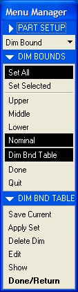
To set a dimension to a particular tolerance limit, we go to Edit, Setup, and then pick on Dim Bound from our Menu Manager when it appears. This will give us the following.

In the DIM BOUNDS menu, we can see options for which dimensions we are selecting. These are:
· Set All – Sets all dimensions in the model to the tolerance limit specified in the next section.
· Set Selected – Allows you to select specific dimensions (such as the length dimension) and only set that one to the tolerance limit specified in the next section.
The next section of options defines the tolerance limit. The choices are:
· Upper – Sets the dimension value(s) to the maximum value based on the tolerance(s) specified.
· Lower – Sets the dimension value(s) to the minimum value based on the tolerance(s) specified.
· Nominal – Sets the dimensions back to their nominal values.
· Dim Bnd Table – Lets you read from a dimension boundary table that you can create. The following figure shows a sample Dim Bound Table.
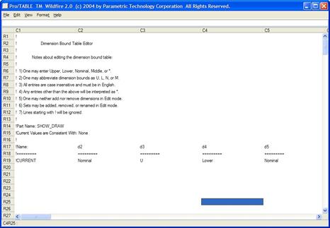
I recommend setting up these tables to make quick work of stack-up analyses. The way they work, you can specify the Set All option, and then pick on the Dim Bnd Table. This brings up the following menu.
Starting from scratch, you would select Edit, which brings up the figure at the top of this page. In the table, the dimension symbol names are listed across the columns. Here, only four of the many dimensions are visible. If we scroll to the right, we would see the rest of them.
For each of the symbols, you can specify whether they should be at the Upper, Lower, Middle or Nominal values. You could set up a table for each type of stack-up you want to try. Then, when you are ready, use the Apply Set to read in one of the tables. Regenerate the model, run your analysis, then apply a different set.
NOTES
Creating notes on the drawing is easy. Demonstrate this, go back to the Show_Draw drawing that we have been working with. We will create a note at the bottom left corner of the drawing.
Before we do this, we are going to first go to our TOP view, and find out the dimension symbol name for one of our radius values. Therefore, double click on the radius dimension that is currently out in the middle of the view (near the large hole). When the properties window opens up, go to the Dimension Text tab, and you should see the dimension name is d7.
Close the properties window. In the drawing toolbar, click on the create note icon, or go to Insert, Note from the menu bar. This brings up the following menu.

The top section of this menu deals with leaders. To create a general note on the drawing, we will use the No Leader option (which is currently the default). If we wanted to make a leader that pointed to an edge or surface, we would use the With Leader option. There is also an ISO leader option, an On Item leader option, and an Offset leader option. These are probably less used, so we won’t cover them in this guide.
Next, we can specify whether we are going to enter the note ourselves, or we are going to import a text file from disk. We will keep the default option of Enter.
The next section defines the orientation of the note. The default is Horizontal, but we also have Vertical, or Angular options as well. We will keep the default option.
The next section only applies if you are using leaders. Since we are not going to use a leader, we will skip this section. The section following this justifies the text, and the section after this allows us to specify a style to use. We will leave the Default option selected.
Finally, we have the option to make the note or cancel out (Done/Return). We will therefore pick Make Note, and then pick down in the lower left corner of our drawing (out in the open area – not on the actual corner of the sheet).
When we do this, the message bar becomes a text field and we can enter the first line of our note. We will enter: NOTES:
When done, click on the <ENTER> key on your keyboard. We are now prompted to enter text for the second line of our note. We want to have a space in the note, so we will hit our spacebar once, followed by <ENTER>. NOTE: If you don’t hit the spacebar, and just hit <ENTER>, you will be done creating the note.
We are now prompted to enter the next row of text. We will type: UNLESS OTHERWISE SPECIFIED, ALL ROUNDS
Hit on the <ENTER> key, and type the last part of the note: AND FILLETS SHALL BE &d7.
Hit the <ENTER> key, and then hit the <ENTER> key once more to complete the note. We will see the following on the drawing.

We can see that instead of “&d7” in our note, we can actually see the dimension value for our radius (.500), and if we go to our TOP view, we can see that the radius dimension is no longer on the drawing view.

Why is this? If you remember, our drawing can not be over constrained with dimensions that come from the model, therefore, if we use the syntax &d# in a note, that dimension that represents d# will transfer over to the note, and disappear from the drawing where it was used.
This same thing works with created dimensions, which are typically &ad#. The only difference is that you can over constrain your drawing with created dimensions, and the system won’t stop you. If you delete the note, the dimension will re-appear on your view.
As I mentioned a few paragraphs back, there are so many possible combinations of leader types and attachments for creating notes that we won’t cover them all in this guide. If you have questions about notes, please don’t hesitate to contact your CAD Administrator or the online help for more information.
Save and close this drawing.
LESSON SUMMARY
Dimensions are probably the most time-consuming entities to place on your drawing. Using shown dimensions, you can save some time in creation, and by applying clean-up techniques (both in sketch mode, and in drawing mode), you can save a lot of time.
Created dimensions are often used when you need to specify manufacturing dimensions that conflict with your current fit, form and function dimensioning scheme, or where no such dimension exists in the model.
Always try to show dimensions that must be “inspection” dimensions. Apply tolerances to your dimensions, and perform stack-up analyses to test your design. You can also embed dimensions into notes and remove them automatically from the drawing.
EXERCISES
None