Lesson 46

Lesson Objective: In this lesson, we will learn how to show axes on our drawing view, and also how to show GTOL Datums. We will have a general discussion on the Show/Erase tool as well.
SHOWING AXES
If your model has holes, slots or cylindrical surfaces, you will want to show axes in your drawing view – especially if you intend to dimension to these axes. All axes should exist in the model prior to showing them in the drawing. Most cylindrical-like features in Pro/ENGINEER generate axes. Full Rounds, for example, do not, so they will need to be added afterwards.
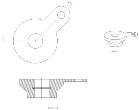
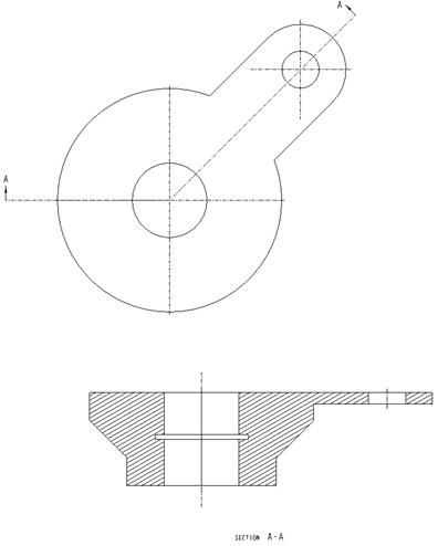
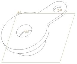
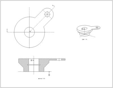
To demonstrate this functionality, we are going to open up a drawing entitled Axis_Model.drw, which initially looks like the following.
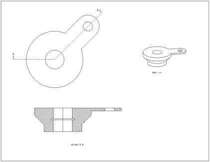
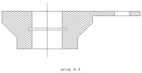
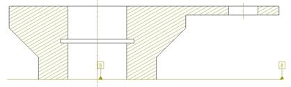
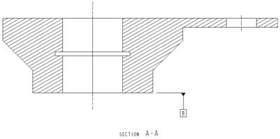
This drawing consists of three views. The upper left view is a general view oriented to the TOP saved view. The second view is a projected section view (using a Full(Align) section type so it unfolds the geometry). The third view is a general view in a TRIMETRIC orientation, and at a ½ scale.
For the first and second view, we want to show the axes that go through the two holes, but we don’t want axes on our general view.
SHOW/ERASE TOOL
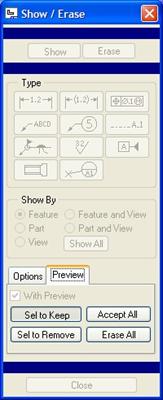
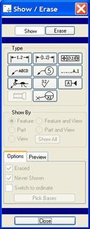
Therefore, to show axes, we will go to View, Show and Erase from the menu bar (or select on the Show/Erase icon in the drawing toolbar). This brings up the following window.
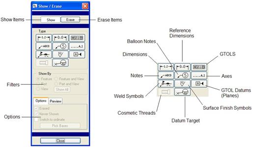
This tool is used to show most of the detail-oriented entities in the model, such as axes, dimensions, notes, GTOLS, etc. The figure above shows what each of the individual buttons are for.
The most important thing to note when you enter this tool is whether you are in SHOW or ERASE mode. The tool will start out in the last mode that was used in the same session.
Once you have selected your mode, you pick on the object button(s) you wish to control. You can show more than one type of entity at the same time, although I highly recommend against it. For a simple model like this, it might be okay, but when you have hundreds or thousands of features in your model, it can get very messy very quickly.
My advise is to start with axes, and then move on to dimensions, and then on to more specialized entity types. Therefore, we are going to pick on the Axes button, which will make the window look like the following.
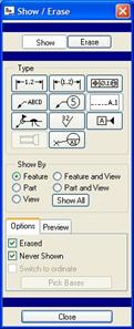
In the Filter region of the tool we have the following options:
· Feature – When you select on a feature in any view, it shows the axis in all views for that feature.
· Part – Shows all of the axes for a selected part (usually use this in assembly mode where you have more than one part)
· View – Shows all of the axes for a selected view. All other views will not show axes yet.
· Feature and View – Shows the axes for the particular feature, but only in the view where you picked the feature. All other features and views will not show the axis yet.
· Part and View – Shows the axes for the entire part in a selected view. Again, this is used more in Assembly mode.
· Show All – Shows all axes in all views. For part mode, this would do the same as the Part option.
Okay – here’s my advice on selecting a filter. If your model is small in terms of the number of features, and the amount of entities that might be shown, then using Show All is faster for getting all of the entities to show up. Then, you can optionally keep or remove entities from the preview, or erase them later. The disadvantage of “Show All” is the fact that it will take you longer to perform a clean-up of entities.
If the model is very complex with a lot of features, I recommend using the Feature or Feature and View options, because you may not want all of the dimensions for the entire part shown. The disadvantage of using these two is that to show all dimensions for an entire part, you would have to pick on each feature in turn, where a “Show All” would do it in one shot. As you show the entities per feature, you can then clean them up and move on to the next feature.
We are going to keep the default of Feature selected, and pick out on the large revolved protrusion as shown in the next figure.
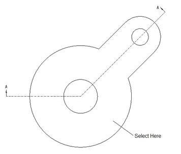
When we do this, an axis will show up in each of the views, as we can see in the next figure.
We could continue to pick more features, but we will click on the middle mouse button at this time to accept our current selection. When we do this, we get the following.
At the bottom of this window, we have four options for dealing with the entities that have appeared on our views. These options are:
· Sel to Keep – (Select to Keep). Only axes that we pick on the views will be kept when we are done, all others will be erased automatically.
· Sel to Remove – (Select to Remove). Only axes that we pick on the views will be erased, all others will be kept.
· Accept All – Keeps all of the axes that we see on the screen.
· Erase All – Cancels the current show/erase by erasing all axes that popped up on the screen.
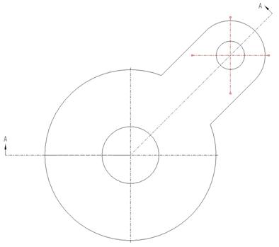
We only want to get rid of the axis that appeared on the general trimetric view. Therefore, we will pick on the Sel to Remove button, and then pick on the axis on the general view. It will highlight red when we select it. We could hold down the Ctrl key and select additional axes to remove, but we are done at this time.
When we click on the middle mouse button to finish selecting objects to remove, we are left with the following.
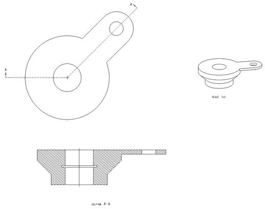
As you can see, the axis is gone from the general view, but still remains in the two other views. Click on Close to get out of the Show/Erase tool. Now, we have some clean-up to do on these axes.
RESIZE AXES
If we zoom in on the first general view we created, we can see that the axis is very small. Normally, when you show axes on a drawing view, the axis lines extend beyond the cylindrical surface to which they apply (and sometimes even longer if the axis represents other items on the model, such as a bolt pattern).
When we zoom in, we see the following.
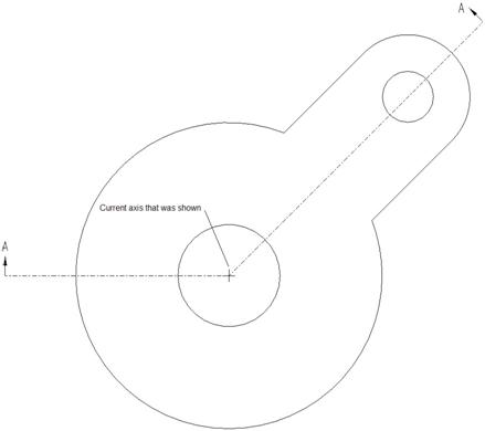
We can see the tiny axis that we just showed on this view. When we pick on the axis, we can see it highlight in red, and little red squares appear at the ends of each of the axis lines, as shown in the next figure.
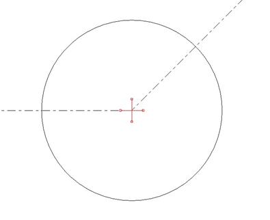
You can drag the axis lines independently of each other by placing your mouse over the square and drag it. The following figure shows such a drag.
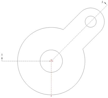
This is useful if you need to extend one or more of the lines further than the others. To resize all of the lines at once, place your mouse over the selected axis until you see four arrows on the mouse icon. Then drag out one of the axis lines. The following figure shows what we want to end up with.
Once you have the axis looking the way you want, click on the drawing outside of the view to de-select it. Our axis on our view now looks like the following.

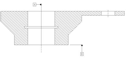
We will go to the cross-section view, and drag out the axis on both sides just to make it a little more clear that this is an axis, as shown in the next figure.
Remaining Axes
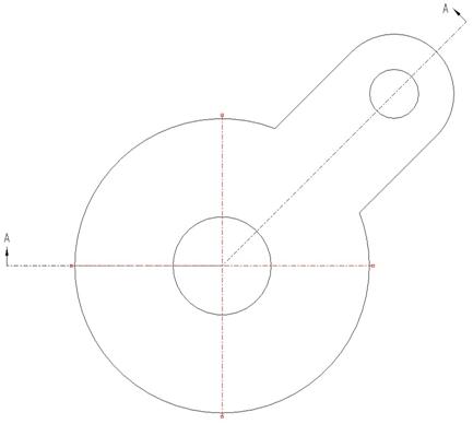
We still have one more axis we have to show for these two views, the one that goes through the hole in the handle. Repeat the same process that we just went through to create the following.
NOTE: You don’t want to have any axes on the second general view, and you may want to use Sel to Keep this time instead of Sel to Remove (fewer items to pick). You also may be wondering why the axis in the big hole showed up again. When creating the handle, a “Use Edge” command was used in the sketch, which grabbed the outer edge of the revolve feature, thus creating another axis for this feature.
ROTATE AXIS
Another thing you may wish to do for your axes, is have the axis lines rotated to line up with the model edges. On our first general view, we might want to do this for the new axis that sits on the handle.
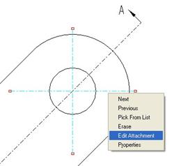
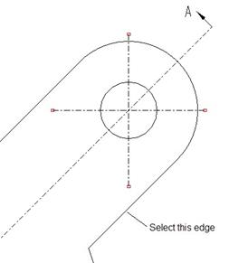
To rotate an axis, you first select the axis, as shown in the next figure.
Next, right click on the axis and select Edit Attachment, as shown in the next figure.
This will bring up the following menu manager.
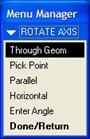
We can use a variety of methods for defining the angle for the axis, but we will pick Parallel on the menu, and then select the following edge.
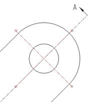
When we do this, the axis rotates as expected.
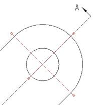
Now, we will resize one of the axis lines to bring it back just outside the small circle, as shown in the next figure.
Click anywhere outside of the view to de-select the axis, and save the drawing.
GTOL DATUMS
If you recall from our Lesson41a drawing, we saw some geometric set datums. These datums were planes created in the model, and then converted over to set datum features. We will go through an example using our current model (Lesson45) to show how to create set datums.
Therefore, open up the axis_model.prt model. Currently, we have all of our default datum planes turned off on a layer. That is okay, because when you create set datums, you should use new datum planes instead of existing default datum planes. Why? In the process of creating the set datums, we will give the datums new names (A, B, C, etc.). We don’t want to rename our FRONT, TOP or RIGHT datum planes, or our default axes, as well in this process.
AXES AS SET DATUMS
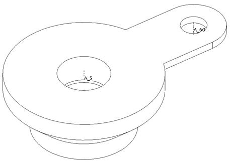
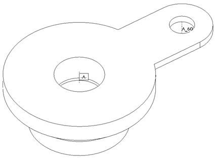
We will start by going to our layers, and turning on the AXES layer, and then save status. Turn on the visibility of axes and you should see two axes on the model, as shown in the next figure.
We want to create a set datum on the A_5 axis. To create a set datum, we will go to Edit, Setup from the menu bar. This brings up the following menu manager.
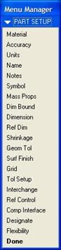
We will click on the Geom Tol command, which brings us to the next menu.
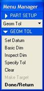
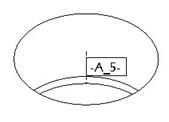
Within this menu, we can create inspection and basic dimensions, and create our set datums. We will pick on Set Datum, and then pick on the A_5 axis on the model. This brings up the next window.
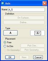
On the model, we can see a box around the dimension, and dashes on either side of the name, as shown in the next figure.
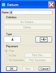
We have two different ways we can place this datum. The first is Free, which keeps it tied to the axis itself. This is the one shown above. The second is In Dim, which ties the datum to a selected dimension (usually a diameter or radius in this type of selection).
We will keep the default of Free selected. You may also notice two buttons in this window. The First button, labeled A, is used to unset the axis if it was previously set as a datum. The button labeled -A- is used to set a datum. We will leave this latter button pressed. The last thing we need to do for our axis is rename it. We will give it a name of A. Click on OK to complete the definition, and we will see the following on our model.
PLANAR SET DATUMS
We will now create a planar set datum. Therefore, turn on the display of datum planes, and then create a new datum plane through the bottom planar surface of our part (not the side with the handle).
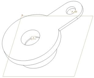
Rename the plane to B. Our model should currently look like the following.
Now, I am going to show you a different way to set datum planes/axes as set datums without having to go through the Edit, Setup, Geom Tol, Set Datum menu structure. Right click on this datum plane in the model tree and select Properties. This brings up the following window.
Click on the -A- button to turn this into a set datum, followed by OK. We will now see the datum symbol on the datum plane on the model, as shown in the next figure.
Now we are ready to show these datums on our drawing. If we switch back over to our drawing file, we can see that our planar set datum is there already.
In fact, we can see two set datums right now. The reason for this is the nature of the cross-sectional view. Since this is an “unfolded” or “aligned” cross-section, it is almost like two separate views in one, and that is why we are seeing two datums. We will pick on the middle datum so it highlights in red, and then using the right mouse button, select Erase. Then, clean up the remaining datum to look like the following.
Now we will show the axis set datum. To do this, go to View, Show and Erase and you get the following window.
To show axis set datums, we actually have to show axes again. Therefore, we will click on the Show button, and then the Axis button. We will use the Show All this time. When we do this, we get the following:
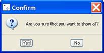
Remember, a show all may give you a very cluttered screen to sift through, so you get a prompt asking if you are really sure you want to do this. We will click on Yes, which will bring back all axes, including ones that we didn’t select before, and the default datum axes as well, as shown in the next figure.
The default option at the bottom of our window is Sel to Keep, and we will keep this selected. On our cross-section view, we will select the box with the “A” inside it, as shown in the next figure.
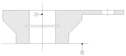
Click on the middle mouse button once you have selected this set datum. The rest of the axes disappear, and we are left with just the newly added set datum for the axis. Move the datum to clean it up as shown in the next figure.
So, you might be wondering why we didn’t need to show the set datum planes, and yet there is a button on the show/erase tool to show these. Actually, these are the only set datums that come on by default. If you erase a set datum, as we have in this lesson, you can use the show/erase tool to bring them back.
Save and close this drawing.
LESSON SUMMARY
The Show/Erase tool allows you to turn on/off many entities in your drawing. In this lesson we saw how to show axes using some of the different ways to use this tool. We also learned how to create set datums for axes and planes, and show them on the drawing.
EXERCISES
None