Lesson 45

Lesson Objective: In this lesson, we will learn how to create Auxiliary and Detailed views.
AUXILIARY VIEWS
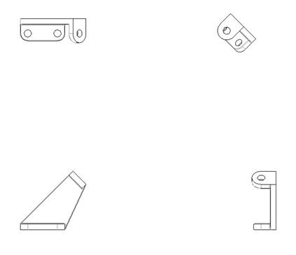
To demonstrate how to create an auxiliary view, we will open up a drawing called Lesson45.drw. It will look like the following.
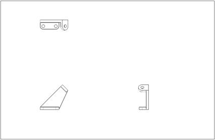
This drawing uses a B size sheet, and the 1abc.dtl drawing setup file has been applied. No drawing format has been applied at this time.
Three views exist on this drawing already. The first view (General View) is the front view in the lower left corner. The second and third views are projected views to make the TOP and RIGHT views in the drawing.
We are going to add an auxiliary view in the upper right corner of this drawing. Therefore, we will go to Insert, Drawing View, Auxiliary from the menu bar. This will give us the following message bar prompt: “Select edge of or axis through, or datum plane as, front surface on main view.”
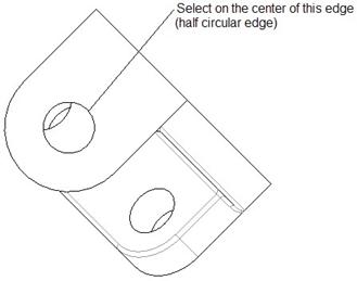
Since an auxiliary view is often created from an angled surface, we will pick on the edge indicated in the following figure.
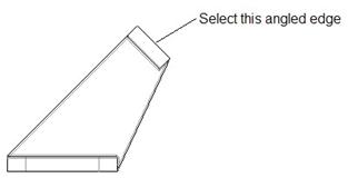
When we select this edge, an orange square appears showing us the location of the view to place it, as shown in the next figure.
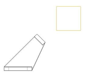
As you move your mouse, you will notice that the view stays in a line normal to the edge that we selected. We will drop the view in the upper corner of the “invisible” square that makes up the views, as shown in the next figure.
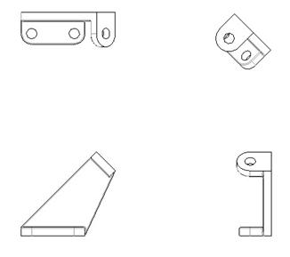
At this point in time, we will drag all of the views in towards the general view to get them a little closer together. This is optional, as we have not added all of the dimensions yet so real-estate might be a problem if the views are close to each other, but we will need some room for our detailed view that we will add next. Our drawing (with the views closer together), looks like the following.
Save the drawing.
DETAILED VIEWS
A Detailed view is a drawing view that represents only a portion of the parent view from which it comes, but it is intentionally scaled independently so we have the ability to “blow up” the magnification of the view to see more detail – hence “detail” view.
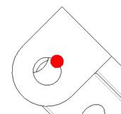
We are going to create a detail view that zeros in on the top of the auxiliary view that we just created. Therefore, we will go to Insert, Drawing View, Detailed. When we do this, we get the following prompt in our message bar: “Select center point for detail on an existing view.” We are going to pick in the following location.
When we pick here, a solid red dot appears on the model, as we can see in the next figure.
And, in our message bar, we see the following prompt: “Sketch a spline, without intersecting other splines, to define an outline.” We are going to sketch a spline (similar to how we did it for the local cross-section boundary in the last lesson) as shown in the following figure.
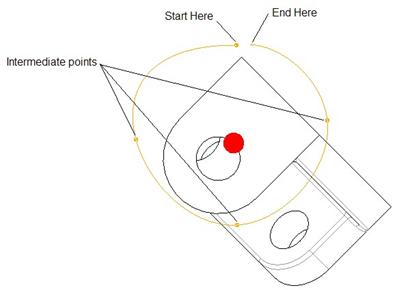
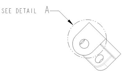
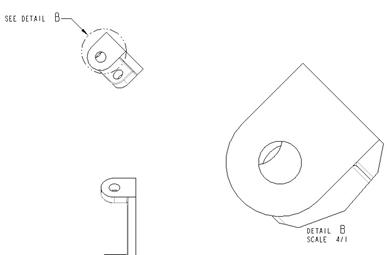
When we pick our last point (indicated by “End Here” in the figure above), click on the middle mouse button, and you will see a dashed circle appear around the region with text indicating “SEE DETAIL A”, as shown in the next figure.
In the message bar, we are prompted to select the center point for the view on the drawing. We will pick out to the left of our existing four views. When we do this, we see the new detailed view, as shown in the next figure.
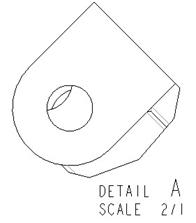
Okay – a couple of things to point out. By default, the new view comes in at a 2X scale to the existing drawing view scale. The boundary of the detailed view is a circle by default. Also, the name of the detailed view is assigned at “A”.
We want to change all of these things at this point.
Scale
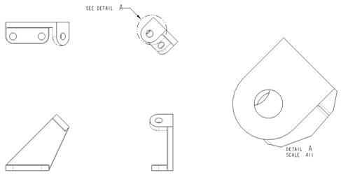
To change the scale of this view, simply double-click on the “2/1” text in the detail view name. In the message bar, type in 4, and then hit the <ENTER> key on your keyboard. The view will enlarge by a factor of 2 again, as shown in the next figure.
NOTE: You must first select the entire note, and then you will notice that the “2/1” text highlights independently. Once you see it independently highlighting, that is when you double-click on it to change the value in the message bar.
View Name
In this drawing, it is okay that the detail name is “A”, because we currently do not have any section views that may already be using this designation. As a general rule, view names should never repeat themselves, even if one is a section and the other is a detail view.
To demonstrate how to rename a view, we will change the name of this view to B. To do this, double click on the “A” note in the view name, and enter “B” in the message bar. The following figure shows the new view name (in both locations). NOTE: You can change the name in either location where it appears.
Boundary Shape
By default, the boundary is approximated into a circle with the minimum radius being the maximum distance from the filled in dot to the sketched boundary at the time we made the view. We can use other shapes for our boundary (Ellipse, H/V Ellipse, Spline and ASME 94 Circle).
To edit this, we will click on the detailed view so it becomes selected, and then right click and go to Properties. This brings up the properties window for this view, as shown in the next figure.
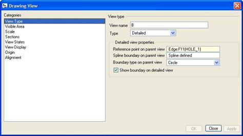
We can (of course) rename the view here as well. On the View Type category, we can see an option entitled Boundary type on parent view. It is currently set to Circle. If we use the pull-down, we can see the other options.
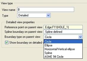
We will select the Spline option, just to show you something different. Click on OK when you are done, and your view will update as follows.
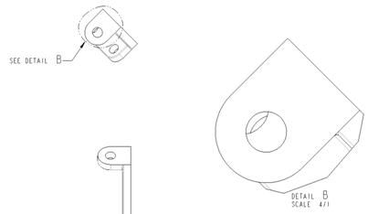
NOTE: You may need to move the text around on the parent view to get it to be the way you want it, as shown in the figure above.
One last thing to mention. In our properties window, we saw a check box labeled Show boundary on detailed view. If our sketched boundary intersects view geometry, leaving this checked will show a solid line where the boundary exists. We can see this in the lower right corner of our detailed view.
If you were to uncheck this option, then the boundary will not show. The boundary edge that is out in space (not touching any of the model) will not show regardless.
Save and close this drawing.
LESSON SUMMARY
An Auxiliary view is a projected view that is normal to an angled surface in the model. A detailed view takes a portion of the parent view that you sketch around and blows it up into an independent view. The boundary can be changed to one of a variety of formats. Both views are accessed through the menu bar.
EXERCISES
None