Lesson 35

Lesson Objective: In this lesson, we will learn about Family Tables.
USAGE OF FAMILY TABLES
Family tables are used to capture “like” models – or models that typically only change in size or minimal feature definition from one part to another. A perfect example of a family table is a family of socket head cap screws. Each individual instance of the screw is only different from a dimensional or material specification.
You can create multi-dimensional family tables (or what is referred to as nested family tables) that can capture a larger family of parts/assemblies. Until you are comfortable working with family tables, I would stick with single level family tables. An example of a nested family table would be to create an entire family of screws.
At the top level, you would distinguish between head types (SHCS, FHD, HHD, etc.). Then, at the second level, you could break each of these into dimensional and material types.
PREPARING THE MODEL
To demonstrate this functionality, we will open up the model called Mounting_Rail, which looks like the following.
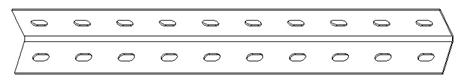
The goal for this lesson is to be able to make different sizes for this mounting rail, and yet maintain a proper slot spacing and number of holes.
Dimension Symbol Names
As you learned in the last lesson (Parameters & Relations), you should rename any dimension symbols that are going to be used in Relations. The same is true for dimensions that will be used in family tables.
In this example, we have already renamed the dimension symbols of the primary features used in both the relations (that we will see in a minute) and the family table that we will create.
The following are some of the key symbol names:
· Length – The overall length of the rail, which is currently at 10”.
· Size – The height of the rail (both sides are equal in size), which is currently 1”.
· Radius – The radius of the inner fillet, which is currently 0.125”.
· Lead_Offset – The spacing from the left edge of the rail to the first slot.
· Spacing – The spacing between slots on the first slot pattern
· Slotnum – The total number of slots in the first slot pattern
· Slot_Length – The length of the lead slot
· Slot_Width – The width of the lead slot.
Relations
Whenever possible, you should use relations before creating family tables. This is especially true if there is a ratio between two or more dimensions that should always exist, regardless of overall size of the model.
This is the case in this model. The spacing of the slots is always 1”, regardless of the length of the rail. Therefore, we need to change the total number of holes when the length changes.
To do this, we could have added the Slotnum dimension to a family table and controlled it there, but then we would have a lot of calculations to do each time we wanted a new size for our rail. Instead, we will do this with relations.
The relations for this model can be found using Tools, Relations, as shown in the next figure.
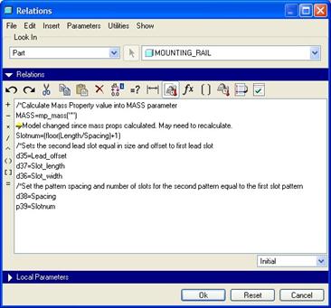
The relation that controls the overall number of holes is the following:
Slotnum=(floor(Length/Spacing)+1)
What this does is first calculate the overall length divided by the spacing. For our current example, the Length=10 and the Spacing=1, therefore this equation results in 10/1 = 10. Then, it adds one additional hole, making a total of 11 holes.
When the length of our rail is an exact increment of 1, such as 10, 11, 12, etc., then we always end up with one slot outside of the model. That is okay, because if our rail has a decimal attachment, such as 12.75”, then it will make a difference.
Floor(Length/Spacing) always rounds the final number down to the nearest integer, therefore, if we have a length of 12.75”, then Floor(12.75) = 12. If we only had 12 slots, then we would have a large portion at the end of our rail that did not have a slot in it (or even a partial slot). Adding the 13th slot takes care of this.
The last portion of this relation sets the dimensions of the second set of slots equal to the first so that the overall impression is that both are identical.
CREATING THE FAMILY TABLE
To create the family table, go to Tools, Family Table from the Menu Bar. When we do this, it will bring up the following interface.
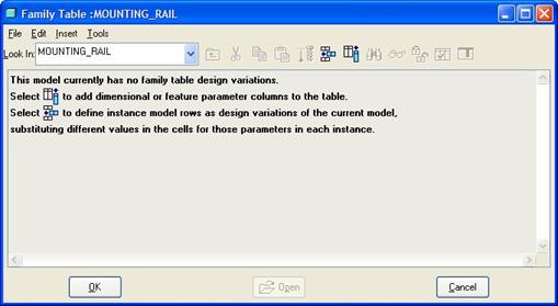
Currently, there are no instances created for this model. Across the top of this window is a toolbar. The first available icon is used to add instances (adding rows to the table). It looks like the following.
![]()
We will click on this icon five times in a row to create five different instances. When we do this, we will see the following.
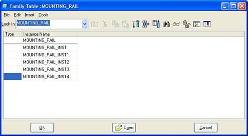
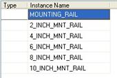
Before we add any dimensions, features, parameters, etc. to our family table, we will change the names of our rails. We are going to create rails in 2” increments starting at 2 and ending at 10. Therefore, we will click in each cell starting with MOUNTING_RAIL_INST and rename them as follows:
We are now ready to start defining the items that vary from instance to instance. We will therefore click on the following icon to add columns to our table.
![]()
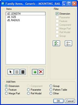
This brings up the following window.
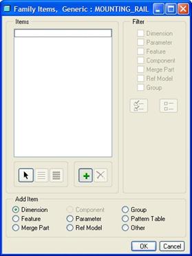
Down at the bottom, you would start by selecting the type of entity you are going to add to the family table. In this case, the default is Dimension, which is what we will use. We will now pick out on the first extrude feature and then pick on the 10.000 length dimension. When we do this, it becomes added to our table, as shown in the next figure.
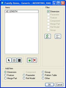
We will also pick on the 1.000 size dimension, and the 0.125 radius dimension. The following shows this window once all three dimensions are added.
We can see our modified symbol names listed next to the original symbol name. This makes it easier for us to identify which dimension is which. If we accidentally added a dimension that we didn’t want, we would highlight it and click on the button with the red “X”.
Next, we will add a parameter to our table. Therefore, click on the Parameter option at the bottom, and you will get the following window.
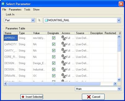
We will scroll down until we find the parameter called Title. Click on this parameter, and then click on the Insert Selected button at the bottom of this window. The TITLE parameter now shows up in our window, as shown in the next figure.
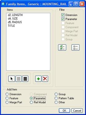
Click on the Close button to close out of the parameters window. We are done defining our family table. You can see in the above figure that we can add features, groups, pattern tables, etc. to our family table, and we can also temporarily filter out what we are looking at by using the upper right corner of this box. Click on OK to return to edit the table.
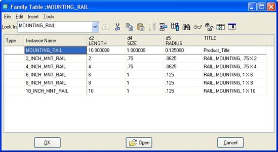
The table now has a column for each of the items that we added, in the order in which they were added, as shown below.
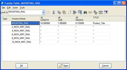
We will edit each cell with the values that we want. The following figure shows our completed table.
Once you have your table filled out, it is time to verify the instances. This is very important before you check them into Pro/INTRALINK. To verify the instances, click on the following icon.
![]()
This brings up the following window.

This window will list all instances, and show which ones have not been verified. Currently all five instances are “Unverified”. Click on the Verify button, and each one will be opened and regenerated behind the scenes. If all goes well, you will be left with a status of “Success” for each instance, as shown in the next figure.
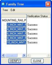
If any fail, it will list that. You will then need to go back and fix the instance. The most common problem with a failed instance is a decimal point error while typing. Once all instances are successfully verified, click on the Close button.
Back in the family table, we can preview our instances by highlighting the instance and clicking on the following icon.
![]()
The following figures show the preview for the 8” and 2” versions of our part.
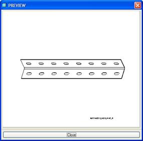
8”

2”
You can spin, pan, zoom, change display type, etc. while in the preview window. When you are done, click on the Close button at the bottom. Once you are happy with your family table, click on OK to complete the family table, and then save your model.
LESSON SUMMARY
The interface for family tables is now more streamlined.
EXERCISES
None