Lesson 210

Lesson Objective: In this lesson, we will learn about Swept Blends.

SWEPT BLEND USAGE
A swept blend is used when you must blend together several sections, but the path that the blend takes must follow a specific trajectory. It is sort of a combination between a general blend and a sweep feature.
Unlike a variable section sweep, you can only use one trajectory, but you can vary the shape of the sections drastically along the trajectory, which you can not do with a variable section sweep.
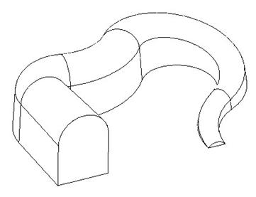
To demonstrate this, we will create the following swept blend protrusion.
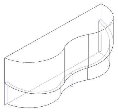
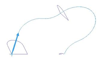
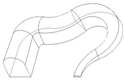
We will open up the Swept_Blend.prt part file in our ProETrain directory. It will initially look like the following.
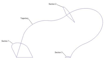
The trajectory will be the long, open ended sketched curve, and the three sections that we are gong to blend are indicated in the order in which we will pick them.
Like the General Blend, it is easier to select your trajectory and sections, although you have the ability to sketch them. For this lesson, we will select the entities.
CREATING THE SWEPT BLEND
There is no icon on the feature toolbar for this tool, and like a regular sweep feature, you have to decide ahead of time what type of material condition are you creating (Protrusion, Cut, Surface, etc.).
We will use Insert, Swept Blend, Protrusion from the menu bar, as shown below.
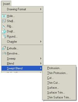
This brings up the following menu.
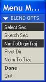
At the top of this menu, we will define how we are going to create the sections. By default, the option Sketch Sec is selected. We have already selected Select Sec in the figure above. This means that when we come to defining sections, we are going to select them instead of sketching them.
The options at the bottom are similar to the ones we have seen in the variable section sweep. These are:
· NrmToOriginTraj – Normal to origin trajectory. We will only pick one trajectory with this option, which acts as the origin.
· Pivot Dir – Pivot Direction. Choose a datum plane or planar surface that the sections will be perpendicular to along the length of the trajectory.
· Norm To Traj – Normal to Trajectory. In this option, you actually will pick two trajectories, but the sections don’t follow both. One of the trajectories will be the one that the sections follow, while the other one determines perpendicularity of the sections.
We are going to keep the first option by default, and then select Done. This will bring up the Swept Blend window, as shown below.
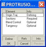
We can see that we are defining the origin trajectory. We have the following menu options that appear.

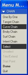
To sketch a trajectory, you would use the Sketch Traj option. We, however, want to select an existing curve or edge as the trajectory; therefore we will pick on the Select Traj option. This will bring up a menu giving us options for how to select the trajectory. We want to select the Curve Chain option, since we are picking on a sketched datum curve.
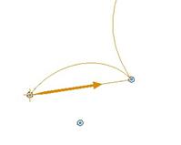
We will then select on the straight portion of the trajectory, shown with the bold red highlight in the figure below. When we do this, one of the ends of the trajectory will have a bold, blue arrow, indicating the start point.
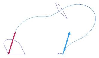
We want to start at the other end, so we will click on Start Point from the menu. A smaller menu appears with the options Next and Accept. We want to click on Next, which will cause the vertex at the other end of the curve to highlight. We will then click on Accept to move the start point to this end, as shown below.
With the start point in the right spot, we will click on Done to move forward. We are now placed into a menu to select our sections.
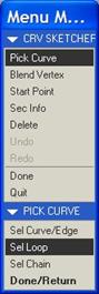
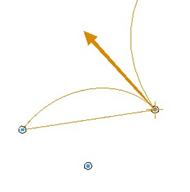
We will keep the default option of Pick Curve selected, but at the bottom, we want to select Sel Loop, which will let us pick the entire closed loop of curve segments that make up the section. We will then pick on the bottom edge of the first section. When we do this, the entire first curve highlights, and a start point arrow appears.
As in all other blends that we have talked about, we want to make sure the start point is in the same location on all of the sections. There is a point on each of the sections that never changes, and that is the one that lies on the trajectory. Therefore, we want our start point to look like the figure below.
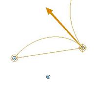
Once it looks like the figure above, click on Done. We see the same menu again, and we want to pick the same options. This time, we will pick on the bottom edge of the second section, and make sure our start point arrow is on the point that lies on the trajectory, as shown below.
Click on Done for this section once it looks like the figure above. In the message window, we are asked if we want to continue selecting sections. We will enter Y. For the third section, we will still use the Sel Loop, and we will pick on the flat edge. When we do this, the start point shows up on the following vertex.
We want to switch the start point to be on the other end of this edge, so it lies on the trajectory. Therefore, we select Start Point from the menu, and then pick on the opposite vertex for this straight segment. It will now look like the following.
BLEND VERTEX
If you look at the first two sections, there are four entities that make up these. There is a straight edge on the bottom, two edges on the sides, and an arc at the top. This third section only has two entities, the straight edge at the bottom and the arc at the top.
We must have the same number of entities for this to work, so we will create two blend vertices. A Blend Vertex is a selected vertex on the section that will force two vertices from the previous section to blend into this one. Since we are eliminating the two side edges from the third section, we need to have the vertices from these edges in section two blend into a single vertex in section three.
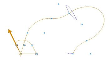
So, we will pick Blend Vertex from the menu, and select the two endpoints of the straight segment. When we do this, a large circle appears around the vertex, as shown below.
Once we have done this, click on Done. At the prompt to create additional sections, type in N. We can now click on OK to complete this feature, as shown below.
There were two other options in the Swept Blend window. These were.
· Blend Control – Specify how the blend will be controlled. You can create an area graph specifying the exact smoothness of the blend. You can also ask it to create more of a linear blend. The default blending method usually gives good results, so we didn’t have to define other options.
· Tangency – If you have existing geometry at the ends of the trajectory, you can specify whether the swept blend should be tangent to these entities. This is very useful if doing this as a surface feature. Since we don’t have any other features in this model, we don’t need to define this option.
LESSON SUMMARY
A swept blend is a great tool to use if you must blend together multiple sections, and control the shape between the sections by a trajectory.
You can select or sketch the sections and trajectory, but it is often easier to select.
Remember to check your start points and number of entities. Create blend vertices where necessary.
EXERCISES
Open up the Swept_Blend2.prt part file, and create a swept blend cut around the bottom rim of the part, as shown below. Use the outside edge as the trajectory, and use the existing datum curves as the sections.