Lesson 200

Lesson Objective: In this lesson, we will learn about Variable Section Sweeps.
VARIABLE SECTION SWEEP DEFINITION
A variable section sweep is an advanced sweep feature that, instead of maintaining a constant section shape and size along the length of the trajectory, is varying along the trajectory by specifying additional trajectories that push or pull the section as it goes.
CREATING A VSS (Variable Section)
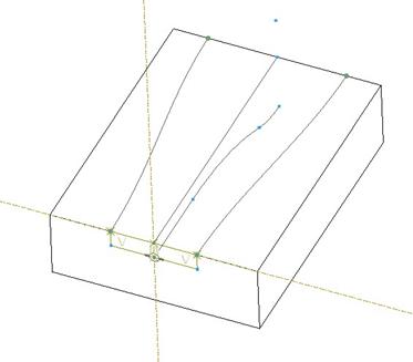
To demonstrate this functionality, we will open up the Variable_Section1.prt file, which initially looks like the following.
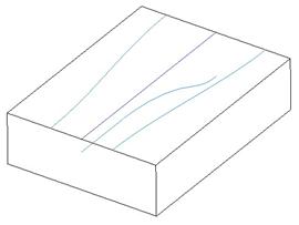
In this example, we are going to create a cut out of the block that is rectangular in shape, but changes size according to the datum curves/sketches that are on the model.
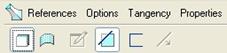
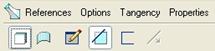
To create a variable section sweep, click on the following icon in the Feature Toolbar.
![]()
This will open up the variable section sweep tool, and its dashboard looks like the following (with the References panel open).
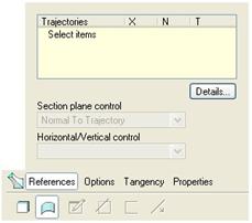
By default, variable section sweeps start out as surfaces. Therefore, we will need to first click on the Solid icon (first icon in the dashboard). Once we pick on this option, select the Remove Material icon. Our dashboard should now look like the following.
We are now ready to start selecting our trajectories. One of the big differences in Wildfire 2.0 is that we don’t have to specify whether it is a curve or an edge chain. We can simply pick on the reference, and it will be smart enough to know whether it is valid or not.
We will begin by picking on the origin trajectory. The first trajectory that we pick in a VSS feature is always treated as the origin. The best trajectory in our model to use as the origin trajectory is the dark blue straight curve on the top of the block. Therefore, we will pick on it. The model will highlight the curve, as shown.
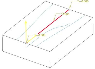
There is a label on the curve that identifies it as the “Origin”. In addition, there are two dimensions and two yellow arrows. The two dimensions can be used to extend or shorten the trajectory for our origin even if the selected trajectory is longer/shorter. It does not change the length of the original curve, only the origin trajectory in this feature.
The yellow arrow that is pointing down the trajectory is the start point. If we were to click on it, we could change the start point to the other end of the trajectory.
The second yellow arrow is used to identify the Horizontal/Vertical orientation when no other trajectories are specified as the “X-Trajectory”. In a regular sweep feature, this would be used to help orient the sketch, as there is only one trajectory.
Our References panel looks like the following.
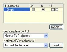
We can see our Origin trajectory listed, and there is a check in the box in the “N” column, indicating that our section, when swept, will be normal to this trajectory. We could change the section plane control to Normal to Projection or Constant Normal Direction using the first pull-down field, entitled “Section Plane Control”.
We will now start to pick our other trajectories. The order doesn’t matter once you select your origin, but for consistency, we will pick the next curve shown below as our second trajectory. Be sure to hold down the Ctrl key when picking this second trajectory – otherwise, you will re-select the “Origin”.
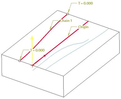
We can see that this trajectory is labeled “Chain 1”, and since it is currently active in the reference window, we can see the two dimensions used to extend/shorten it.
We will now hold down the Ctrl key again, and select our third trajectory, shown below.
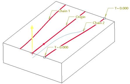
This trajectory is now labeled “Chain 2”. Hold down the Ctrl key once again, and select our fourth trajectory, shown in the next figure.
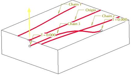
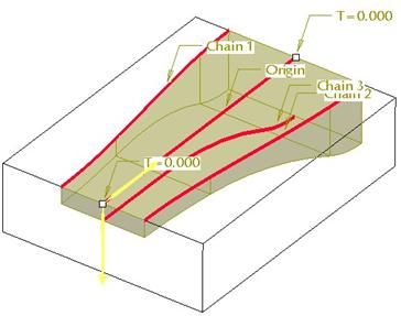
It is labeled “Chain 3”. We now have all of our necessary trajectories. Our References panel looks like the following.

We can see all four trajectories listed with their labels. We can also see a column entitled “X”. This column allows us to specify a trajectory from our list to act as our “X-Trajectory”. We will click in the check box for “Chain 2”, so it looks like the following.
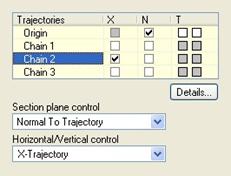
When the check mark appears, you will notice that our Horizontal/Vertical control field has changed to X-Trajectory. This allows the application to automatically line up the Origin and the Chain 2 start points on the same horizontal when inside sketch mode.
We are now ready to create our section. Therefore, we will click on the pencil and paper icon in the dashboard (just to the left of the “Remove Material” icon). This brings us into our sketch, which initially looks like the following.
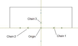
The figure above illustrates the location of the different start points for these trajectories, based on the start point for the origin. It is upside down from how we were looking at it before, but that is okay, because we can always rotate the sketch to see how we are looking at it.
We are going to sketch a rectangle that has corners that touch the end of “Chain 1” and “Chain 2”, and is controlled by the Chain 3 for its height, as shown in the next figure.
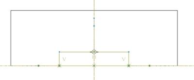
If we go back to a rotated view, we can see exactly where our section sits with respect to the trajectories.
When we click on the check mark to complete the sketch, we will see the profile of our VSS feature, as shown below.
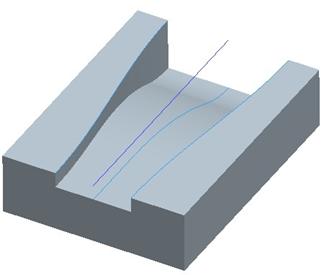
The downward arrow in this preview indicates the material removal side. We will click on the green check mark to complete our feature. Our model now looks like the following.
CREATING A VSS (Constant Section)
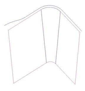
In this next section, we are going to see how to create a regular sweep using the Variable Section Sweep feature. To demonstrate this, open up the Variable_Section2 part, which looks like the following.
We are going to cut out a special lip around the front top edge of this part, but we only want it to be a certain location. Therefore, we will start by going into our variable section sweep tool. Make sure that you select the Solid and Remove Material options from the dashboard, as shown below.
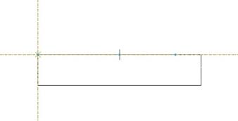
Next, pick on the front, top edge so it highlights as shown in the next figure.
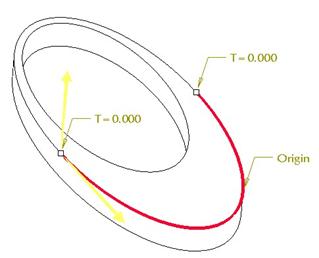
At the two ends of the highlighted edge, we can see the T=0.000 dimensions that allow us to extend or shorten the length of our trajectory. We will shorten the trajectory by 2” on each end, therefore, we will double-click on the 0.000 dimension, and change it to -2.0 for each end.
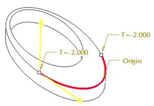
The result is shown in the following figure.
Next, we will go to the dashboard and pick on the Options slide-up panel, and select Constant Section, as shown in the next figure.
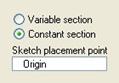
We actually may not need to do this to get our final result, but I would get in the habit, because there may be a time down the road where this feature could fail, because it may be looking for more than one trajectory (Variable section option), and we only want a single trajectory (Constant section option).
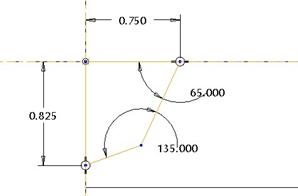
Now, we will click on the sketch icon, and when we are placed into sketcher, we will see the following.
The intersecting dashed lines represent the start of our trajectory (where the yellow arrow was). If you are not sure how you are looking at the part, you can rotate it, and then return to the sketch view after that.
We will sketch four lines and dimension as shown.
When we finish our sketch, and rotate our model, we can see the dynamic preview (another advantage of using a VSS over a regular sweep, which currently does not have a dynamic preview).
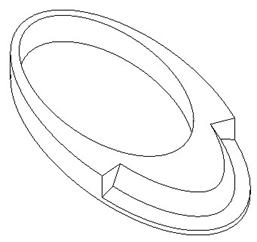
The completed model looks like the next figure.
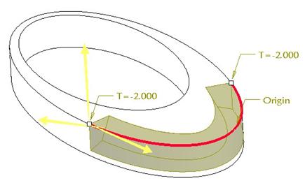
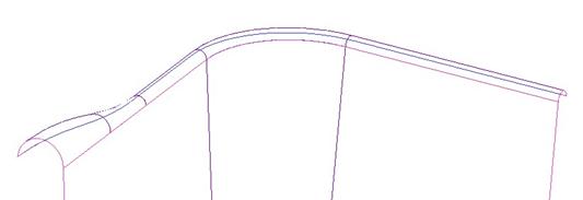
Had we needed more control over the end points of the trajectory, we would need to use the regular sweep feature and sketch our trajectory on top of the existing model edges. The following figure shows an example of a case where a variable section sweep would have to be combined with additional features to accomplish what a regular sweep would do.
LESSON SUMMARY
The variable section sweep is a very powerful tool to take a standard swept type feature, and stretch and pull it in different directions by defining datum curves that the section will ride along.
Be sure to create your datum curves ahead of time. If you happened to forget one, you could pause the feature and create one on the fly.
Use the variable section sweep for regular swept features if you don’t need to add inner faces
EXERCISES
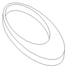
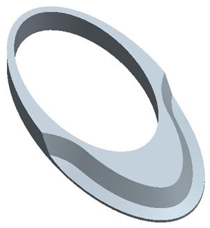
Open up the basket part in our ProETrain folder. It should look like the following.
We want to create a surface variable section sweep at the top of the existing surface as shown below.
The section for the rim profile is a semicircle that is normal to the top rim of the existing surface as it goes around.