Lesson 190

Lesson Objective: In this lesson, we will learn about Patterns.

PATTERN USAGE
Patterns are used to replicate a feature (or group of features) multiple times in a repetitive manner. Patterns can be as simple as three holes with equal spacing in a row, or one-hundred bumps on a surface to create a non-skid texture.
There are three primary types of patterns. These are:
· Dimensional – You want to pattern an entity in a certain direction. A dimension is selected that already goes in that direction. You provide the incremental spacing between entities, and the number of entities that will result.
· Table – You create a table based on selected driver dimensions. The table can indicate non-uniform patterns. You can put as much or as little information into a pattern table as you need.
· Fill – You create a feature, then pattern that feature within a boundary that you sketch. You can change the shape, spacing, angle and visibility of the instances in that pattern.
Within a Dimensional pattern, you also have the ability to define one of three attributes. These are:
· Identical – Each instance is completely identical to the one that is being patterned. The pattern can not intersect itself or leave the current surface boundary that the lead entity is located on.
· Varying – You can vary different aspects of the entity, such as depth, diameter (for a hole), etc. for each instance in an incremental fashion. The instances are able to leave the current surface boundary, but they can not intersect themselves.
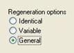
· General – There are no restrictions on this type, but it takes longer to regenerate than an identical pattern. If you can’t get an identical or varying pattern to work, try setting it as a general pattern first. If this does not work, then there are bigger issues at work.
CREATING PATTERNS
The pattern tool is commonly activated using the right mouse button (either on the feature itself or on the model tree). You can also get to patterns through the Edit menu, or using the following icon in the Feature Toolbar.
![]()
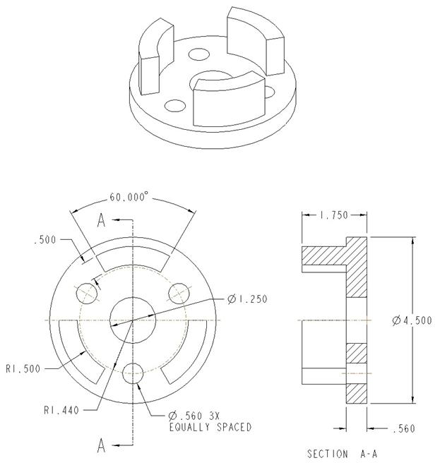
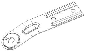
You must start by picking on a feature to pattern, otherwise the tool is not active. To demonstrate the pattern tool, we will start with the Hole_Definition part that we saved from lesson16. It will look like the following.
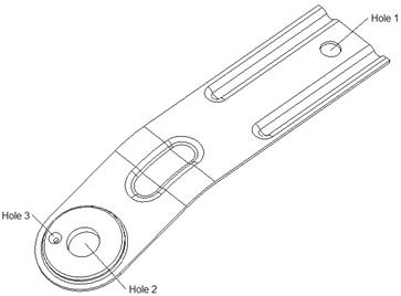
We created three different holes in this part in lesson 16. The first (Hole 1) was a linear hole. The second (Hole 2) was a coaxial hole, and the third (Hole 3) was a radial/diameter hole. The following figure shows these holes.
We will start by clicking on the Hole 1 feature in our model tree (or the hole that corresponds to “Hole 1” in the previous figure). Once selected, click on the Pattern tool. The dimensions for the hole feature should appear on the model, as we can see in the next figure.
The dashboard appears and looks like the following.
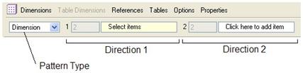
By default, most features will assume a dimensional pattern type. This is the common one in 2001 – which requires you to pick a dimension that drives the first and second directions. Other pattern types exist in Wildfire 2.0, but we will start with the standard Dimensional pattern.
Therefore, we start by picking on the dimension that drives the first direction of the pattern. We will pick on the 1.000 dimension. When we do this, a field appears right beneath the selected dimension, as we can see in the next figure.
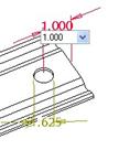
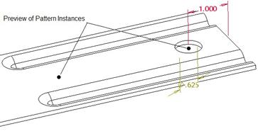
We will use this field to specify the increment between holes. Type in 3.25 and then hit the <ENTER> key on your keyboard. You should now see little black circles indicating where the holes will be when completed as shown in the next figure.
If we open up the Dimensions panel, we will see the following.
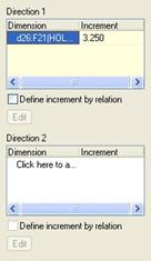
We can see the dimensions and increment values defined for the first and second directions. We can also see that we can define the increment by relations. Currently, we have defined a single driving dimension for direction1, and the spacing is 3.250. If we go to the Options panel, we can see the three different classifications of patterns.
We will leave these alone right now. Click on the green check mark to complete this pattern, and you will see the following.
Next, we are going to create a radial pattern using Hole 3. For this pattern, we will use a reference instead of an actual dimension to drive the pattern. Therefore, start by picking on the hole in the model tree and then click on the pattern tool. We can see the dimensions show up in the next figure.
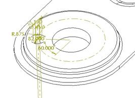
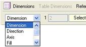
We could select on the 60.000 dimension to drive the angle, but we will demonstrate a different type of pattern, called Axis. In the dashboard, use the first pull-down field to change the option from Dimension to Axis, as we can see in the next figure.
Once we select Axis, we must select a datum axis or edge that will act as the pattern reference. We will turn on our datum axes and select the A_10 axis. Once we do this, we can see a different look on the model.
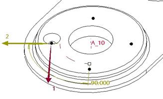
There are now two arrows, one for the first direction (maroon arrow labeled “1”) and one for the second direction (yellow arrow labeled “2”), as we can see in the figure above. We can also see the default increment is currently 90.000 degrees, and there are four black dots representing four holes.
In the dashboard, we can see the following.
![]()
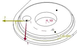
There is still a section for first direction and second direction. We will change the total number of instances from 4 to 3, and the angle from 90.000 to 120.000, as shown below.
![]()
This change is also reflected on the model itself.
We will now click on the green check mark to complete this hole pattern. Our model will now look like the following.
Save and close this model.
FILL PATTERN
The next pattern type that will discuss is the Fill pattern. This is new in Wildfire, and offers a huge benefit to users that create very large identical patterns that fill in a grid on a model. For example, suppose you are creating a non-skid surface with all of the little diamond shape bumps on it. This would be one way of doing that.
The advantage of a fill pattern over an identical dimensional pattern is the fact that you don’t have to stay within a rectangular grid, and the second is that the lead feature doesn’t have to have any dimensions associated with it, nor do you have to even keep the lead pattern.
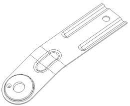
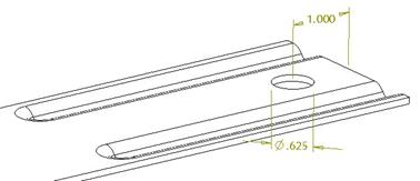
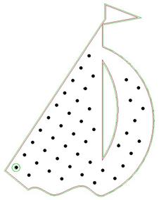
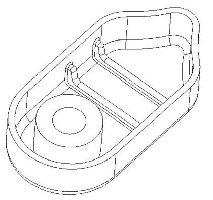
To demonstrate this pattern type, we will open up the model entitled Boat. It will initially look like the following.

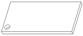
This is a bath mat, and requires suction cups along the bottom to prevent it from sliding. If we turn the model around, we can see one of these suction cups that we created.
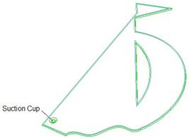
If we zoom in close on this model, we can also see a sketch feature. This sketch feature defines the area that is going to be filled. We can either use a sketch feature (as we are in this example), or we can sketch a shape once we get into the pattern itself.
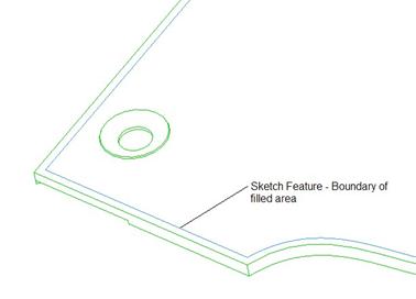
If we look at the model tree, we can see that we created the suction cup as a revolve feature, and we used an “on-the-fly” datum plane, which caused the features to be grouped together.
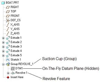
With a regular dimensional pattern, this would be necessary to include the offset dimension for the plane to be tied to the feature being patterned. In a fill pattern, however, we don’t need the datum plane at all. We could even ungroup this current group and pattern the revolve feature all by itself.
Instead, we will simply pick on the Revolve 1 feature in the model tree and then click on the pattern tool. When the dashboard appears, switch the pattern type to Fill, as shown in the next figure.
When we do this, the dashboard will change to look like the following.

We must start by defining the fill boundary. If we needed to sketch a boundary, we could right click in the working window and use the Define Internal Sketch option. Instead, we will pick on the sketch feature on the model.
NOTE: If you are going to use a pre-defined sketch (as we are in this example), it must come before the feature being patterned in the model tree. This is because the model is rolled back to the time just before the feature was created for the pattern.
When we pick on the sketch feature, we will see the following in the model. Go to a BOTTOM view for the rest of this example.
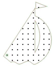
A grid of black circles appears on the model. This is the preview for the pattern. In the dashboard, we have a variety of options to chose from for defining the shape of this pattern. The first field to the right of the sketch definition is the shape of the pattern. The default is Square, which gives you the effect above. There are other shapes, such as Triangle, Diamond, Circle, Spiral, Curve, etc. that give you different results. Try each one until you find the one you want.
In our example, we are going to stay with the Square option. The next field to the right is the spacing between instances. We are going to change this value to 0.750. The next field is the distance from the boundary that we sketched/selected. We will use a value of 0.300 for this fill. The last field is used to rotate the entire grid about the lead instance. We will use a value of 57.000 degrees to line the suction cups up with the long angled edge.
The dashboard, when completed will look like the following.
![]()
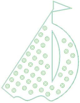
The preview of the pattern will look like the next figure.
If we wanted to remove one or more of the instances from the resulting pattern, we would click on the black circle and turn it white. We, however, are going to keep each of these instances.
When we click on the green check mark, each of the instances will regenerate, and then we will be left with our final pattern, as shown in the next figure.
Save and close this model.
TABLE PATTERNS
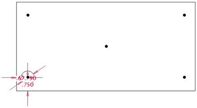
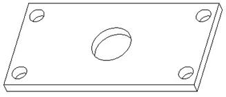
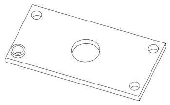
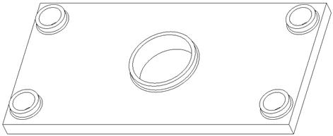
The next pattern type that we will look at is the Table Pattern option. We will demonstrate this functionality with the Plate3 model, which looks like the following.
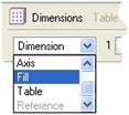
We are going to start by picking on the hole and then select the pattern tool. When the dashboard appears, change the pattern type from Dimension to Table, as shown in the next figure.
When we do this, the dashboard will look like the following.
The first thing we must do is select any dimension we want to control in the table. I find it best to pick them in the order you want to see them in the columns of the table. Therefore, we will pick the 0.625 “x” dimension, followed by the 0.750 “y” dimension, and lastly the 0.750 diameter dimension.
Once all three dimensions are selected, we will click on the Edit button next to the “TABLE1” field. This brings up the table editor, which will look like the following.
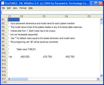
We can see four columns. The first is used to identify the hole by a unique incrementing number. The first hole that we selected represents “1”, therefore, we will start with “2” in the second row.
The remaining columns are our three dimensions that we selected, in the order in which we selected them.
I always find it easier to sketch out the hole pattern on paper prior to filling out the table to make it easier to fill out. My sketch for this hole pattern might look like the following.
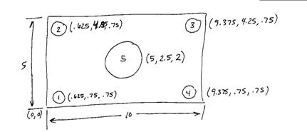
Using this information, I will fill out the table as follows.
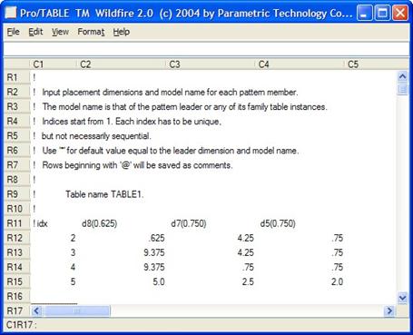
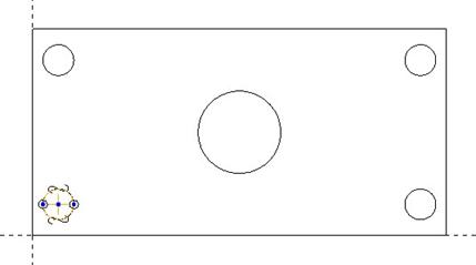
Once the table is filled out, I will select File, Exit from the menu at the top of this window. This saves and exits the table. Back in the model, we will see the preview of this pattern, which looks like the following.
At this time, we could create more than one pattern table for this hole. The reason you might do this would be for different family table instances, or to try out different patterns until you know which one will work for you.
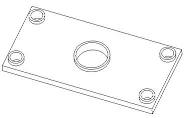
We will click on the green check mark to complete this pattern. Our final model will look like the following.
Save this model for the next pattern type.
REFERENCE PATTERNING
A reference pattern is a feature pattern that follows an existing pattern. In order to make this work, the feature you are trying to pattern must be tied to the lead feature of the existing pattern in such a way that it could be translated to each of the instances of that pattern.
To demonstrate how this works in Wildfire 2.0, we will continue to work with the Plate3 model that we have open. We are going to add two features that will both be referenced patterned. The first will be an extruded thin protrusion. Start by going to the extrude feature, and be sure to select the solid and thin material options, as shown below.
![]()
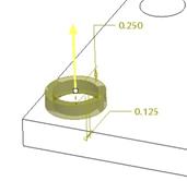
Change the wall thickness to 0.125, as we can see in the above figure. Next, use your right mouse button to Define Internal Sketch. For the sketching plane, use the top surface of the plate, and accept the RIGHT datum plane facing towards the Right. Inside the sketch, use the “Use Edge” tool to select both halves of the lead hole (the one in the lower left corner), as shown in the next figure.
Once we complete the sketch, be sure to flip the material side to the outside of the hole, and change the depth to 0.25. The preview will look like the following.
Click on the green check mark to complete this feature, which looks like the following.
Now, select the extrude feature and then click on the pattern tool. Since this feature is already tied to the lead hole in the hole pattern, the default type listed is Reference, as shown in the next figure.
Click on the green check mark to complete this pattern, and our model will update as shown in the following figure.
Notice that the diameter was controlled by the hole pattern, so it got bigger around the center hole as it should.
The next feature will be a round at the base of the extrude feature on the lead hole. The radius will be 0.05, as shown below.
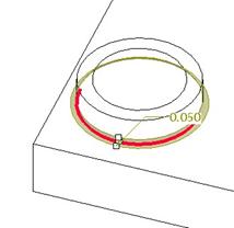
Once you finish this round, select it in the model tree and click on the pattern tool. This time, the dashboard will not open. Instead, it will automatically pattern the round to all of the instances.
Rounds and Chamfers do this automatically. The following figure shows the resulting model once the reference pattern is done.
LESSON SUMMARY
Patterns are great tools to reduce the amount of repetitive work you might incur otherwise. You need to build in the proper dimensioning scheme so you have dimensions available to drive pattern directions, sizes, etc.
In dimensional patterns, you define the instance spacing and number of instances. In table-driven patterns, you spell out exactly the location and size based off of references that the lead entity used. In a fill pattern, you sketch a boundary that the fill resides within, and then you indicate size, shape and orientation.
To successfully group or reference pattern, all entities must be tied only to the lead feature being patterned first (or first in the group). If they reference stationary, non-moving references, the pattern will fail.
EXERCISES
Open up the Headset part that we have worked with in the past, and pattern the rib and all of its rounds, as shown below. The spacing for the ribs is 1.25 inches.
HINT: Since we have not learned how to create a group by combining already created features, you will not be creating one for this exercise. You will, however need to find out which feature drives the 1.25 spacing dimension and pattern that first.