Lesson 170

Lesson Objective: In this lesson, we will learn about the Shell Feature.

SHELL USAGE
The shell feature is designed to take a solid part, and hollow it out to create a thin-walled part. Any exposed surface that is not selected to be removed will get a uniform thickness applied to it.
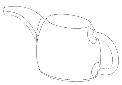
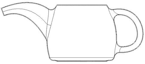
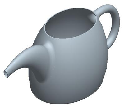
Some surfaces can be specified with non-default thicknesses if necessary. To demonstrate the shell feature, we will open the Shell.prt part, which looks like the following.
If we look at the default cross-section for this part initially, we can see that it is a complete solid, as shown in the following figure.
We are going to hollow this part out so water will actually be able to fill it, and pour from it.
CREATING THE SHELL
To create a shell, click on the following icon in the feature toolbar.
![]()
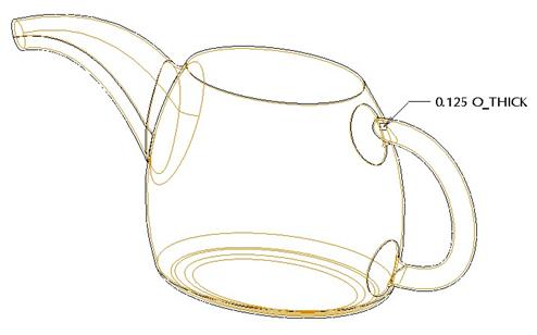
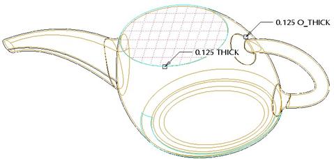
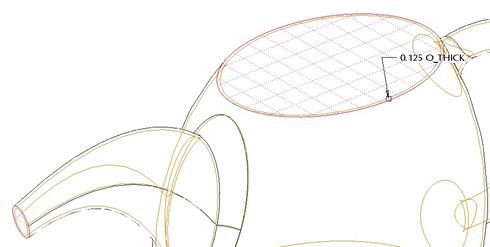
We will instantly see a preview of the shell, and an overall thickness value. Our thickness might be too large initially to see the preview, which means that if we were to accept the default thickness, our shell would fail. We will modify the thickness to 0.125, and then we will be able to see our preview, as shown below.
The dashboard for a shell feature looks like the following.
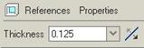
It is pretty simple. We only have a few things to define. In the icon row, we will define the overall thickness, and the side of the material the thickness is being added to. We can actually shell outwards if we wanted to.
If we open up the References panel, we will see the following.
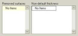
Initially, no surfaces will be removed, and there are no “Non-Default Thicknesses” defined. In other words, if we accept the feature right now, we will have a completely hollow, but closed part. We will accept it right now to show you what I mean.
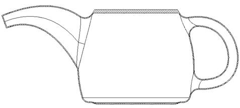
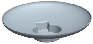
After we accept this, we will go to a FRONT view and look at the cross-section again. We can see that the part is hollow, but we can also see that it is closed the entire way around the part. So if water were in this part, it would have to have been poured as it was molded shut.
We will edit the definition of this feature in the model tree to make some changes. The first change we will make will be while we still have a completely hollow but closed model. In the References panel, click on the field for Non-Default Thicknesses, then select the top flat surface of this part, as shown below.
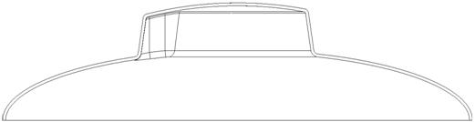
We can see another dimension appear on this part. If we change the thickness for this surface to 0.5, accept the part, and then look at the cross-sectional view again, we would see the figure at the top of the next page.
Any external surface can have a non-default thickness as long as it is not tangent to any other surfaces. Had we had a round at the top of this model where the flat surface met the side domed surface, then we would not have been able to perform this operation. Actually, we wouldn’t be able to remove it either.
We will edit the definition once more. Go into the References panel again. In the Non-Default Thicknesses field, right mouse click on the surface that is listed, and select Remove. Then, in the Removed Surfaces field, click on the words “No Items” to activate this field.
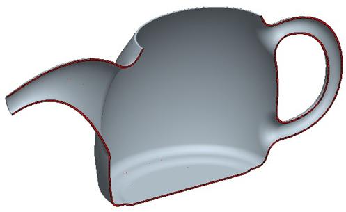
Pick the top flat surface, and the surface at the end of the spout to remove them, as shown in the following figure.
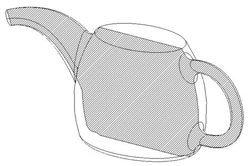
When we accept this part, and shade the model for better clarity, we can see that we have a hollow part, as shown in the figure at the top of the next page.
If we were to go back to our cross-section and use the clipping tool (Select Display, Set Visible, and then select Clip Front, we would see the following.
LESSON SUMMARY
Use the shell tool to hollow out a complex part. The important thing to note is that you will want to use this feature later in the model, after you have defined all features that will need to be hollowed out.
If you create a shell early in the part, then you might want to consider using surfaces instead, and thicken the surfaces later. We will see how to do this in an upcoming lesson.
Select surfaces to remove unless you want to design a blow molded part, and select non-default thicknesses, as long as they are not tangent to other surfaces that must be at the default thickness.
EXERCISES
Draft1
Open up the Draft1 part that we created, and add a 0.1” round to both the top edge and the middle edge, as shown below.

Next, hollow out the model, removing the bottom surface with a wall thickness of 0.0625”, as shown below.
If we look at a cross-section through the middle of the part, it looks like the following figure.
Save and close this model.
Headset
Open up the Headset part file that we created in Lesson 11, and add a Coaxial hole and Shell feature, as shown in the following figure.
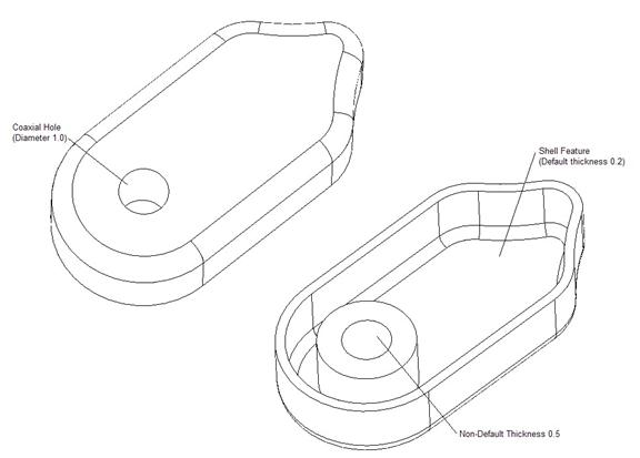
HINT: You may need to create a datum axis first for the coaxial hole.