Lesson 160

Lesson Objective: In this lesson, we will learn about the Hole Feature.

HOLE USAGE
This is another widely underused feature that should be used more often. Many people use extruded cuts or revolved cuts instead of holes, but many of the straight holes or even standard holes do not need to be sketched, and that will save time (both in regeneration and in the user’s time).
There are two main types of holes:
· Straight – The profile is either a plain circle extruded to a certain depth, or you can sketch a profile that creates a revolved cut.
· Standard – Select from industry sized holes (UNC/UNF, etc.)
Once you pick the type of hole you are going to create, you can place the hole using one of the following methods.
· Linear – Hole lies on a plane or planar surface and is located from two references (similar to a datum point on surface).
· Radial (Cylindrical) – Hole lies on the outside of a cylindrical surface, measured from a reference that is perpendicular to the cylinder’s axis, and located about the axis by some angle reference.
· Radial (Axial) – Hole lies on a plane or planar surface, but is located about an axis normal to that surface. Dimensions are radius or diameter around axis, and an angle through the axis.
· Coaxial – Hole lies along a datum axis and starts from a specified plane or planar surface to a desired depth.
CREATING A HOLE FEATURE
The Hole feature is located on the Feature Toolbar in the same group of blue icons as the round, chamfer, rib, shell and draft, and represents the last of the pick-and-place features covered in this guide. The icon looks like the following.
![]()
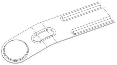
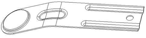
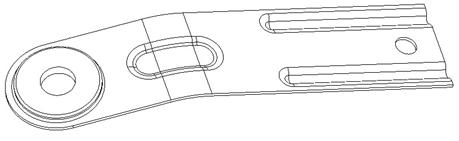
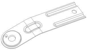
To demonstrate the hole functionality, we will open up the Hole_Definition part, which initially looks like the following.
When you create holes, you generally have four types of placement: Linear, Radial, Diameter and Coaxial. We will use the next sections to show these different types.
LINEAR HOLE
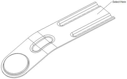
We will start by clicking on the hole feature, and then we will click on the model in the location shown below.
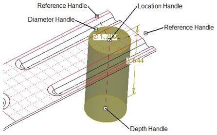
A preview of the hole appears on the model, as shown in the next figure. For a linear placement, there are a number of different drag handles that appear on the hole feature. They are shown in the figure.
Our dashboard looks like the following.
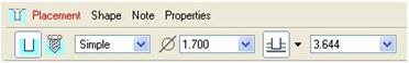
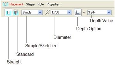
Depending on the type of hole you are creating, you will see different options in the dashboard. For a straight hole (circular cross-section along the entire length), the options represent the following.
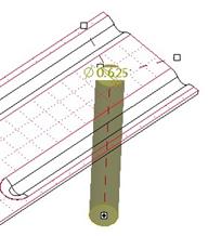
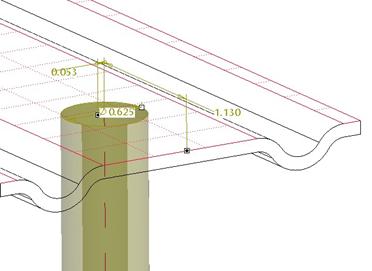
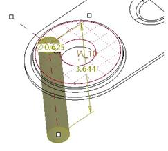
For this first linear hole, we will change the diameter to 0.625 and change the depth option to Through All. Our preview will look like the next figure.
We still have two drag handles that need to be addressed. We will drag the two handles over to the following references.
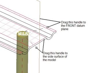
Once we do this, we will see two dimensions on the model.
In the dashboard, we will click on the Placement slide-up panel, which looks like the following.
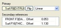
We can see the two references and the respective dimensions. We can also see a middle column that defines the relationship to the references. For the FRONT datum plane row, we will click on the word “Offset” and change the option to Align, and change the remaining offset dimension to 1.000, as shown below.
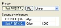
This will make the center of the hole line up with the FRONT datum plane, as we can see on the model preview.
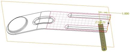
Now we will click on the green check mark to complete this first hole, which will look like the following.
COAXIAL HOLE
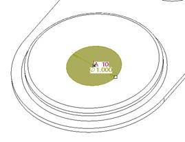
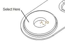
We are going to create another straight, simple hole. The first thing we are going to do is turn on the display of axes. Next, we will create a new hole and pick on the axis A_10 that is going through the large circle on the end.
You will see an outline of the hole that is lined up with the axis that we selected. We will change the diameter value to 1.0, and the depth to Through All. When we do this, our preview looks like the following.
The “depth” of the hole seems to have gone to zero – even though it isn’t. The reason it does this is that there still is not enough information to fully define this hole. To see what is left, we need to expand the Placement panel, which looks like the following.
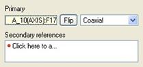
With a coaxial hole, the primary reference is the axis that we picked. The hole knows it is lined up with the axis, but it doesn’t know where it starts from. This is the Secondary Reference. Therefore, pick in the Secondary References field, and then pick on the large, flat, circular surface. The preview now looks like the following.
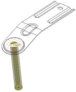
Click on the green check mark to complete this hole. The model now looks like the following.
RADIAL/DIAMETER HOLE
The next hole we create will demonstrate the Radial and/or Diameter placement, but we will also shake it up a bit and switch from a straight, simple hole to a standard hole. Therefore, we will start by creating a new hole feature, and then pick on the following surface.
The hole will initially preview like a Linear placement, as we can see in the following figure.
Before we start dragging handles, we should open up the Placement panel, and use the pull-down field at the top right to change from Linear to Radial, as shown in the next figure.
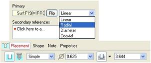
In the figure above, you can see the four placement options. In this example, we use Radial, but we could pick on Diameter and the rest of these steps would be identical. The difference between “Radial” and “Diameter” is how it is dimensioned for the drawing.
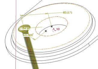
Once you pick on Radial, you must select additional references. Therefore, click into the Secondary References field to make it active, and then pick on the A_10 axis that we picked for the last hole. This will create a radius dimension from the axis to the center of the hole, as shown below.
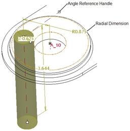
Change this radius dimension to 0.875, as shown in the above figure. The second drag handle must be tied to a datum plane or planar surface that either passes through the A_10 axis, or is parallel to an imaginary plane that would pass through the axis. Therefore, we will drag the reference handle over to the FRONT datum plane.
When we do this, an angle will appear on the preview, as we can see in the next figure.
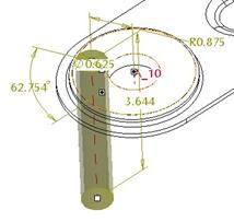
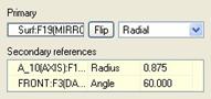
We will modify this angle dimension to 60.0. The Placement panel will look like the following.
Now that we have successfully placed this hole, we will change it to a standard hole. NOTE: You could have selected standard to begin with, but I think it is easier to make the standard hole once it is fully placed, otherwise, you won’t see the correct shape in the preview.
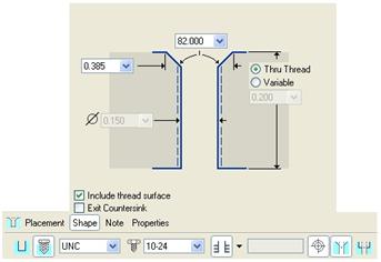
Click on the Standard Hole icon in the lower left of the dashboard. This will change the dashboard to look like the following (with the Shape panel expanded).
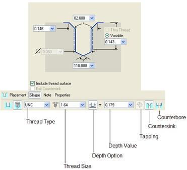
For the Thread Type field, we will keep the UNC option. Other options include UNF and ISO. For the Thread Size field, use the pull-down to select a 10-24 thread. For the depth option, we will pick on the Through All icon. This will make the Depth Value disappear.
At the end of the dashboard icons, we will keep the Tapping and Countersink options selected. Up in the Shape panel, we want to change the depth of the thread to Thru Thread, so the threaded surface goes along the entire length of the tapped hole. We will leave the angle and diameter for the countersink alone, but we could change this if we needed. Our dashboard should now look like the following.
If we look at the preview on the part, we can see the shape and size has updated to reflect this standard hole. If we had not placed it fully, it would still look like a big yellow cylinder.
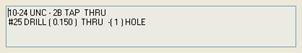
If we expand the Note panel, we can see the standard not that it creates by default. We can edit and add to this note. This note can be shown in the drawing to save us some time re-creating it.
We will now click on the green check mark to complete the hole. The model will look like the following.
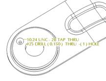
To hide the view of the note on the model, we can go to Tools, Environment and uncheck the 3D Notes option. Our model will now look like the following.
Save and close this model. We will come back to it in the lesson on Patterns.
SKETCHED HOLES
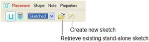
The last option we have for the hole feature is a sketched hole. It is created by starting with a straight hole. In the dashboard, use the first pull-down field to change from Simple to Sketched. When we do this, the dashboard looks like the following.
The sketch must meet the following requirements:
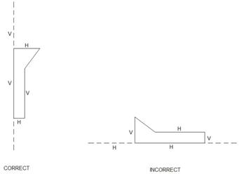
1. Must have a vertical centerline that acts as the axis of revolution
2. Must only be a half-model of the hole (one side of the centerline)
3. Must be closed
The “vertical” centerline is important to remember. Even if you are making a hole in the side of a block, where normally you would sketch a horizontal profile, you still make it vertical in this feature. The following figure shows the correct and incorrect way to do this.
LESSON SUMMARY
Hole features should be used over extruded or revolved cuts. Placing the hole is simple and straightforward once you know what you need to select, and you can pick from standard, industry sizes and take the guesswork out of knowing the exact thread diameter to use.
As you saw in this lesson, you can mix and match hole placement types and hole types. But perhaps the biggest benefit to using the hole feature is when you go to pattern, which we will see in a later lesson.
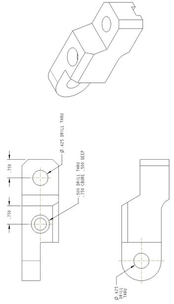
EXERCISES
Open up the Hole_Exercise.prt part and add the three holes shown on the figure on the next page.