Lesson 9

Lesson Objective: In this lesson, we will learn about the Revolve Feature.

REVOLVE DEFINITION
The Revolve feature is created by revolving a sketched profile around an axis of revolution. The angle and direction can be controlled independent of the sketch.
CREATING A REVOLVE FEATURE
The Revolve feature is very similar to the Extrude feature (Lesson 6) from the way that it is created. The biggest differences are in the depth options (fewer for the Revolve feature) and the sketch itself (only a half sketch with a centerline that acts as an axis of revolution).
The steps for a revolve feature with an internal sketch are:
1.
Use Insert,
Revolve from the Menu Bar, or select on the ![]() icon in the Feature Toolbar.
icon in the Feature Toolbar.
2. Select one of the feature types (Solid, Surface, Cut and/or Thin).
3. Hold down the right mouse button and select Define Internal Sketch.
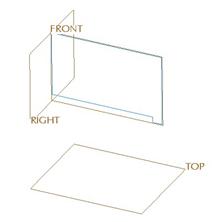
4. Select the sketching plane, horizontal/vertical reference and orientation in the Sketch window.
5. Sketch the profile to be revolved – making sure you only sketch half of the feature and a centerline that acts as an axis of revolution. Click on the blue check mark to finish the sketch.
6. Select the depth option and enter depth value (if blind).
7. Accept the feature.
When using external sketches, you either need to have a centerline defined in the sketch that will be picked as the axis of revolution, or you need to specify a datum axis or straight edge that lies in the plane of the sketch to act as the axis of revolution.
The steps for a revolve feature with an external sketch are:
1. Select the Sketch Feature (either in the working window or in the model tree).
2.
Use Insert,
Revolve from the Menu Bar, or select on the ![]() icon in the Feature Toolbar.
icon in the Feature Toolbar.
3. Select one of the feature types (Solid, Surface, Cut and/or Thin).
4. If a centerline was not used in the Sketch Feature, use the Placement slide-up panel to define a datum axis or edge as the axis of revolution.
5. Select the depth option and enter depth value (if blind).
6. Accept the feature.
EXAMPLE 1 – Internal Sketch
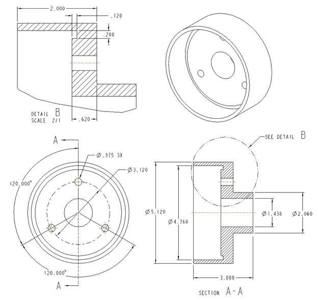
In this example, we will create a revolve feature that uses an internal sketch. To demonstrate this, open up the part entitled Bearing1. It contains a single sketch feature, which we will use later.
The following figure shows this part.
We are going to create a new revolve feature by clicking on
the revolve icon ( ![]() ).
Inside the feature, the dashboard for the revolve feature looks like the
following.
).
Inside the feature, the dashboard for the revolve feature looks like the
following.
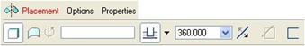
As you can see, the dashboard for the revolve feature looks very similar to the extrude dashboard. We will keep the default feature type of “Solid” and then we will right mouse click in the working window and select Define Internal Sketch.
When the sketch window appears, click on the Use Previous button to sketch on the same plane as the first Sketch feature. Click on Sketch from this window to proceed into sketch mode, and sketch the following profile (don’t forget the vertical centerline sitting on the existing vertical reference).
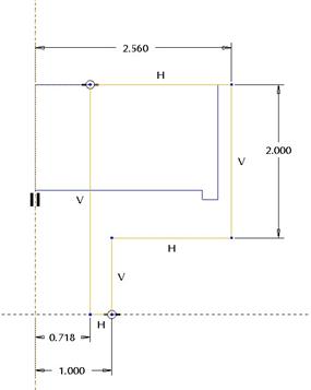
In the figure above, the sketch is shaped like a “P” with all straight edges and sharp corners, and the top of the “P” is tied to the top edge of the sketch feature.
When finished with the sketch, click on the blue check mark. We will now see the preview of the feature.
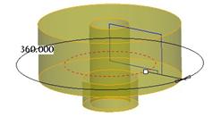
As with the extrude feature, we can see a drag handle on the angular dimension that we can dynamically drag to see the model update. Under the depth options, we only have the following options: Blind (specify angle), Symmetric, and Up to Selected. We will leave the depth option at 360 degrees.
We will click on the green check mark to complete this feature. Our model currently looks like the following.
EXAMPLE 2 – External Sketch
In this example, we will finish this bearing by cutting out the middle using the existing sketch feature. To do this, we will first start by selecting the sketch feature from the model tree so it highlights in read on the model. Next, click on the revolve feature icon.
In the revolve feature, we do not see a preview yet, because we currently do not have a centerline in the sketch feature to act as an axis of revolution. Until the feature definition is complete, our dynamic preview will not appear, indicating to us that we have not defined enough yet.
In our dashboard, we can see a field that is used to select the axis of revolution, as shown in the next figure.
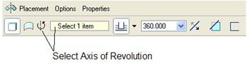
This field is currently highlighted in yellow. This means that we can go ahead and select the datum axis or edge to use. If it were not highlighted in yellow, we could pick once inside this field to make it active.
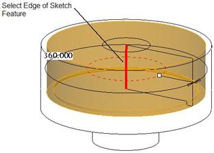
Once the field is active, we can pick on the axis or edge to use. In this case, we have the Z_AXIS datum axis in our model tree that would work. We can also select the inside edge of our sketch feature, since it lies in the plane of the sketch, and it lies at the center of our model.
We will select the edge, as shown in the next figure. When we do this, the dynamic preview appears as shown.
There is only one thing we have to do for this feature, and that is to select the Cut icon to remove material from the model. The preview will change to show a cut instead of a protrusion, and then we can click on the green check mark to accept this feature.
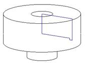
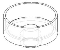
The model now looks like the following (in hidden line mode).
LESSON SUMMARY
The revolve feature is not very different from an extrude feature in terms of the menu picks to create it. The biggest differences lie in the rules for the sketch and the depth options.
When sketching, be sure to create or specify an axis of revolution, and sketch on only one side of this axis. You can also use an existing edge or axis in the model for the axis of revolution if you do not wish to sketch one.
When specifying depth, remember that it is an angle in degrees.
EXERCISES
Create the part below using a combination of extrude and revolve features. Create datum geometry if necessary.
Bearing2