Lesson 8

Lesson Objective: In this lesson, we will learn about Datum Planes, Datum Axes, Datum Points, and Datum Coordinate Systems.

DATUMS – WHAT ARE THEY?
Datum features are widely used in the creation of other features. They are lightweight, don’t affect mass properties, can be hidden when you don’t want to see them, and very powerful in providing necessary ties and references for other features.
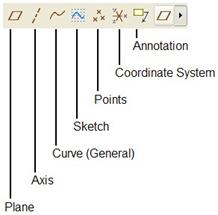
The most common datum feature types are accessed in the feature toolbar by selecting the very top icon in this toolbar. When we select this icon, we see the following datum feature types.
DATUM PLANES
When we create a new part or assembly, we see datum planes already built into the model, as shown for a part file below.
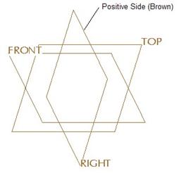
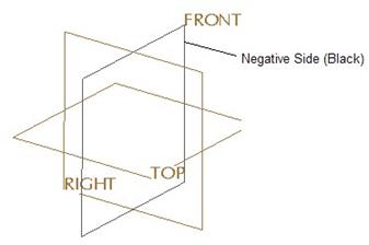
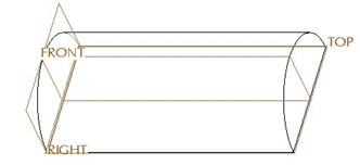
As indicated in the figure above, datum planes have two sides, a positive side and a negative side. The positive side (if you are using the default system colors), is brown. The negative side is black (or actually, a very dark gray – but we’ll consider it black for this training guide). When we are in a default orientation, we can see the positive sides for all three default datum planes. If we rotate the model slightly to see the back side of the FRONT plane, then we can see the negative side, as seen in the figure at the top of the next page.
To turn on/off the display of datum planes, click on the ![]() icon in the system
toolbar.
icon in the system
toolbar.
The positive side of the datum plane is the one that is used when picking orientation references. For example, if we pick on the TOP plane as a sketching plane, we know we will be looking at the TOP plane in the sketch. If we pick the FRONT plane as a sketcher reference, and pick Bottom as the orientation, then the brown side of the FRONT plane will face towards the bottom of the screen in sketch mode.
Datum planes are widely used for sketch planes, sketch reference planes, sketcher references, depth references, cross-section planes, etc. They are probably the most used datum feature in Pro/ENGINEER.
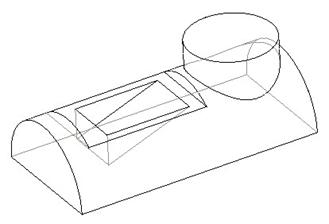
To demonstrate the creation method, we will create the following part.
Before we do this, however, we will change a setting that will allow us to see datum planes when we spin the model. Typically, datum planes temporarily turn off until you stop spinning, panning or zooming.
To change this setting, go to View, Display Settings, Model Display. This will bring up the following window.
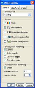
In the middle of this window is a section entitled “Display While Reorienting”. The only items that are checked by default are Surface Mesh and Orientation Center. We want to check Datums, so datum features become visible when we spin.
Now, we will create this part, and call it Dtm_Planes. We will create the part using a start part so we have our default datum planes, as we can see below.
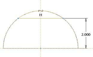
The first feature that we will create is the semi-circular extruded protrusion that forms the main shape of this part. We will use the RIGHT datum plane as a sketching plane and pick the TOP plane to face towards the Top as the sketching reference. Our sketch will look like the following.
The display of datum planes was turned off in the previous figure to see the sketch easier. Once we are done the sketch, we want to extrude to a depth of 10.000 inches. Our first feature looks like the following.
Be sure your RIGHT datum plane is at the left side of the model. If not, edit the definition, and change the direction of feature creation by clicking on the yellow arrow in the dynamic preview.
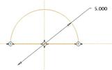
Our next feature will be a datum plane that is offset the RIGHT plane by an amount of 4.00 inches. Therefore, we will pick on the datum plane icon in the datum flyout icon. This will bring up the following window.
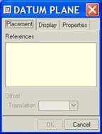
The first tab, entitled Placement is active. We are asked to pick references to define the plane. The datum plane creation tool is pretty smart. Depending on the type of reference we pick, it will assume the most logical choice for creation.
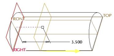
Therefore, if we pick on the RIGHT datum plane, we should see the preview of a plane that is parallel and slightly offset from the RIGHT plane. Drag the white square out towards the right, and you will see it moves the preview of plane, as shown below.
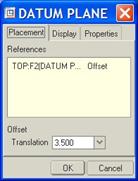
In the Datum Plane window, we see the following.
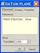
The RIGHT datum plane is listed in the References field, and to the far right is the type of creation method it assumed, which is Offset in this case. Down in the bottom, we can see the offset value, which shows in this figure as 3.500. We will change the value to 4.000 (either here in this window, or on the model).
The second tab in this window is entitled Display, and if we click on it, the window will look like the following.
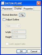
You can use this tab to change the positive side of the plane. In this window, it is called the Normal Direction, and there is a Flip button next to it. There is also an option to Adjust Outline, which allows you to resize the datum plane. By default, it assumes the size of the model. I recommend you let it resize itself.
The third tab is entitled Properties, and looks like the following.
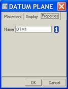
This tab is used to rename the datum plane, or get information about it. We are going to go ahead and click on OK to finish creating this offset datum plane. Our model should now look like the following.
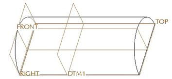
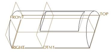
Now that we have this datum plane, we can create our first extruded cut feature. We will use the new datum plane (DTM1) as the sketching plane, and face the TOP plane towards the top again as the sketcher reference. Our sketch will look like the following.
Extrude this cut to the right of the datum plane a distance of 5.00 inches. The model will now look like the following.
Our next datum plane will be another offset plane, a distance of 3.5 inches up from the TOP plane. Click on the datum plane tool, then select on the TOP plane. It should automatically assume an offset creation type.
Make sure it is going above the TOP plane, and change the distance to 3.5. Our datum plane will look like the following once we create it.
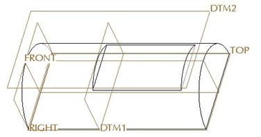
Use this new datum plane (DTM2) as a sketching plane for our next extruded protrusion feature. Pick the RIGHT datum plane to face towards the right. Create the following sketch (with datum planes turned off for easier viewing).

Once we accept this sketch, go back to a default view. The
feature is probably trying to extrude up from this plane. If so, click on the
yellow arrow to flip the direction so the feature is going down. Then, change
your depth option to Through Next ( ![]() ). When you accept this feature, your
model will look like the following.
). When you accept this feature, your
model will look like the following.
Our final feature will be the cut that is angled. We could create this cut by extruding symmetrically about the FRONT datum plane, but then we wouldn’t learn another method for creating datum planes.
Therefore, we will create a new datum plane. This time, we are going to use two references to create the plane, an edge to go Through, and a surface to measure an Angle from. Therefore, pick on the datum plane tool. First, pick the TOP datum plane. It will initially assume an offset, as we can see from the datum plane window.
To add additional references, hold down the Ctrl key on the keyboard, and select them. To get an angled plane, we need a reference that acts as an axis of rotation. Therefore, we will also select the following edge (using the Ctrl key).
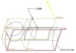
Once we select the edge, we see the Datum Plane window update to show the new creation type applied.
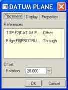
We can see the “Through” condition, and a rotation angle in the bottom. You will want to look at your model to see how the angle is being measured. Often times, the order you pick the references, as well as the references themselves determine how the angle is measured. Since we picked the TOP datum plane (whose positive side is pointing upwards), and an edge, the angle is measured from the brown side of the datum plane. Therefore, we can enter a value of 20 in the rotation field.
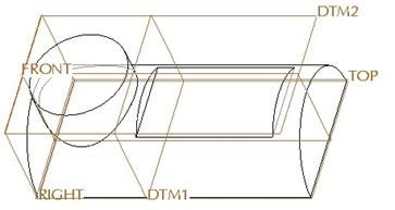
The dynamic preview of the plane will look like the following.
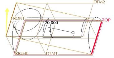
We will click on OK from the datum plane menu to finish off the plane. The model will look like the following now.
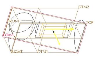
Now that we have this plane, we can create our cut. Use the top surface of the first cut as the sketching plane, and face the left side surface towards the bottom. The figure below shows the references we are picking.
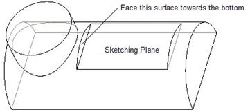
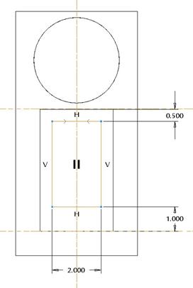
In our sketch, we want to take advantage of symmetry, and put in a vertical centerline on the vertical sketcher reference. When we sketch our rectangle, we will make sure to look for the little arrow symbols that show it is symmetric about this centerline. Our sketch should look like the following.
Once we are done sketching, go to a default view to see the
dynamic preview. We want to make sure the direction is going down, then change
our depth option to To Selected ( ![]() ), and pick the angled datum plane that
we just created. The dynamic preview (in No Hidden model), will look like the
following.
), and pick the angled datum plane that
we just created. The dynamic preview (in No Hidden model), will look like the
following.
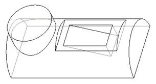
It may not look like it is going to angle down, but if we were to click on the Full Preview icon (the eyeglasses) or accept the feature, we would see that it does stop at the datum plane, as shown in the final model image below.
You can also create datum planes using other references. The following describes the most common methods and references for creating datum planes:
· Through – Create a datum plane to be co-planar with another datum plane or planar surface. Pick on a Datum Plane or Planar Surface as the only reference. When window shows offset, change the value in the window to “Through”, as shown below. Another set of references would be an edge that lies in a single plane, but has at least two directions to it, such as the edge of a cylinder.
· Offset – Create a datum plane offset an existing plane or planar surface. Pick on a plane or planar surface as the only reference. The default type should be “Offset” in the window. Enter the offset value.
· At Angle – Create a datum plane through an edge or axis and at an angle to another plane or planar surface. Pick on a plane or planar surface for one reference and an edge or datum axis for the other reference. Enter the angle.
· Parallel – Create a datum plane parallel to another plane or planar surface through some selected reference. Pick a plane or planar surface as one reference to determine parallelism, then pick on a datum point, vertex, edge, axis or coordinate system as the second reference to determine the location.
· Through Points – Create a datum plane through three datum points or vertices. Pick on three points or vertices or a combination to determine plane.
DATUM POINTS
Datum points are most commonly used for creating other datum entities, such as an axis, plane or curve. Datum points can also be used as sketcher references or for assembling two components into an assembly.
To turn on/off the display of datum points and their tags (names), click on the following icons in the system toolbar.
![]()
The left icon is used for turning on/off the point completely. The icon on the right is only used to turn on/off the point names (tags).
We will open the model Dtm_Pac for an example, and we will show all of the most common methods for creating datum points. To create a datum point, click on the datum point icon in the datum flyout icons. We will see the following window.
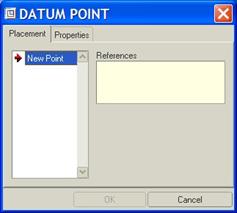
We can create as many different points as we want in a single datum point feature. This is different from the datum plane tool where we could only create one plane at a time. For each point that you create, you select references.
The Properties tab is used to rename the entire datum point feature (not each individual point created).
ON SURFACE
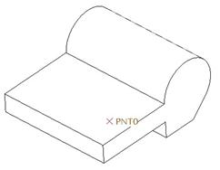
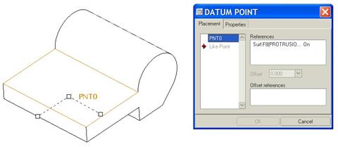
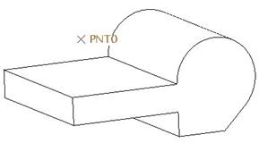
This is a datum point that lies on a selected surface, and its location is measured from two references. To create this, click on the datum point tool, and then pick anywhere on a surface (planar or otherwise). The following figure shows a sample surface pick to place a point, and the Datum Point window when you select on the surface.
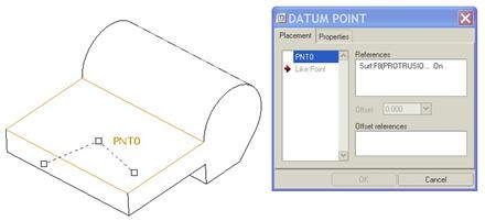
The point shows up on the surface along with three white squares. The square next to the point name (PNT0, in this case), is used to show the location of the point. You can drag this square to locate the point on the surface.
The other two white squares are used to tie to references to locate the point. We will start by dragging the right-most square until it comes to the side surface and snaps there. The model and window will look like the following once we let go of the mouse.
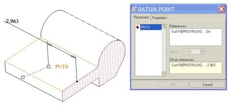
We can see the white square has gone away, and is replaced by a filled dot. This dot shows us that we are lying on that surface edge. The window also reflects this by listing the first Offset Refrence in the field at the bottom of the window.
We will drag the other white square over to the front surface, as shown below.
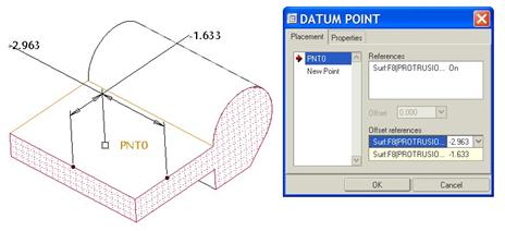
This white square should also be replaced by a filled dot, and the other offset dimension and reference shows up in the window. We would now edit the values of these offset dimensions. To create a new point, we would click on the New Point item in the left column of the window. To complete this datum point feature, click on OK.
The completed point looks like the figure at the top of the next page.
OFFSET SURFACE
This is a datum point that lies offset a surface by a specified amount, and located from two references. The creation method is very similar to an “On Surface” with the addition of an offset distance and direction.
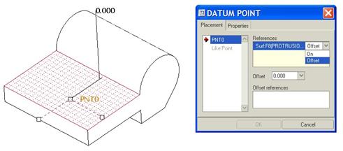
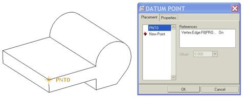
The following figure shows a sample surface pick, and the resulting window.
Just like the “On Surface” point, this starts out the exact way. It even assumes the “On Surface” constraint type. To change this, click where you see the word On, and change it to Offset, as shown below.
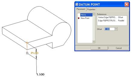
A third dimension appears on the model, and a field for the Offset has become active in the window. We will drag the locating squares to the same surfaces that we did before, then enter the offset value as 1.5, and change the locating dimension to those shown in the following figure.
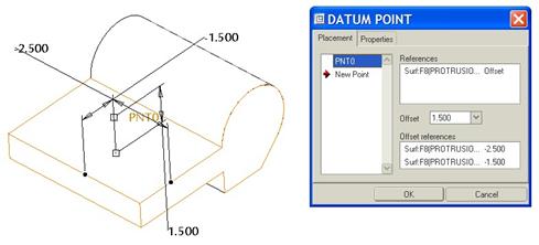
When we see the point as we intended, we click on OK to finish the datum point feature, or click on New Point to create additional points. The final point looks like the following.
ON VERTEX
This is a datum point that lies on the end of an edge or edge segment. You create this by clicking on the datum point tool, then pick on any vertex in the model. The following figure shows the pick and the window that result.
If we click on OK now, we would have a datum point at this corner vertex. Instead, we will continue with this same window to show the next type.
OFFSET VERTEX
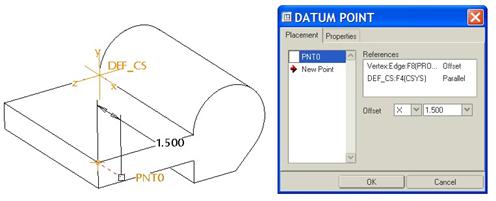
From the last figure, we had picked a vertex to place the point, and the window indicated a constraint of On, which placed our datum point exactly on the selected vertex. If we change the type from On to Offset, then we must pick another entity that defines the offset direction.
We will hold down the Ctrl key and select the edge just below the highlighted vertex, we see the following.
We can enter an offset distance of 1.5, as shown above. The constraint of Parallel applied to this selected edge means that the point will offset from the vertex parallel to the direction of the edge.
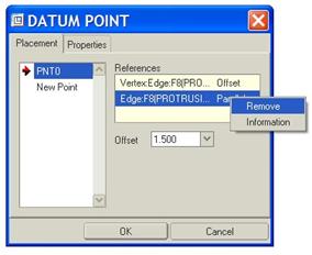
Now, let’s try a different offset reference. First, right mouse click over the word Parallel and select Remove, as shown below.
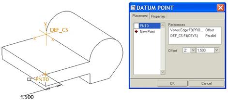
Now, we’ll hold down the Ctrl key and select the DEF_CS coordinate system from the model tree. We see the following in the window and on the model.
Next to the Offset field, we can see another pull-down that currently indicates “X”. This is letting us select which axis of the coordinate system is driving our offset direction. We can change this to “Z” as shown in the following figure.
We will now remove this reference the same way we removed the edge. Once it is removed, we will hold down the Ctrl key again, and this time select the top surface. We will see the following.
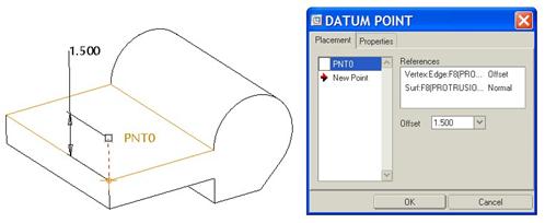
Now, the reference becomes a surface and the offset direction is normal to the surface. As we have demonstrated, you have the ability to select a wide array of references to determine the offset direction.
ON CURVE
Another common point creation is to locate the point on a datum curve or existing edge. We will demonstrate this by selecting the top, front edge of the model. Our model and window will look like the following.
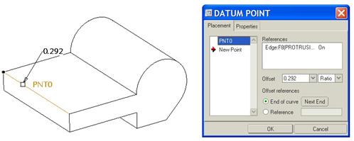
When you select a curve or edge as the reference, you get a variety of options to further refine your point definition. The first is to determine whether the distance is a ratio or a real value. The ratio option represents the percentage along the edge or curve where the point resides. For example, if you wanted the point to be at the exact midpoint of the edge, you would enter a ratio of 0.5.
Real represents the actual distance along the curve the point resides at. For example, suppose you want the point to be exactly 1.5 inches in from the back left surface. You would change the Ratio option to Real as shown in the following figure.
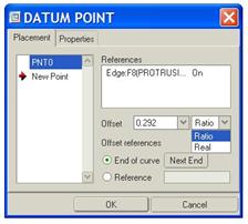
Then, you would enter a value of 1.5 in the offset field.
Once you have determined how the dimension value is being measured, you can pick your reference that the dimension value is coming from. In this window, we can see that the dimension is being measured from the End of Curve. If you want the opposite end to be used, click on the Next End button.
Or, if you want to use a datum plane or other reference other than one of the endpoints, select the Reference option, then select the actual reference on the model. Using the Reference option means that you are using a Real dimension value instead of a ratio.
AT CENTER
This creates a datum point at the center of a circular edge, such as the edge of a cylinder or a hole. To create, click on the datum point tool, then select on the circular edge. Initially, it will assume an “On Curve” constraint, as shown in the following figure.
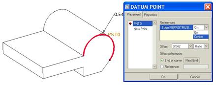
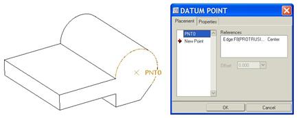
As the figure above illustrates, we want to change the On value to Center. This will remove all other options, and place a point at the center of this circular edge, as shown below.
SKETCHED
The previous points were created using the datum point icon in the feature toolbar. This is the first of the point definitions that can only be accessed through the menu bar. Go to Insert, Model Datum, Point, Sketched. This will bring up the Sketch window to select a sketching plane and a sketching reference. We will pick the top flat surface as a sketching plane, and then select the front surface to face towards the bottom.
Inside our sketch, we will use the sketcher point icon ( ![]() ) and pick the
location on the surface for the points. Dimension the points in whatever style
you need.
) and pick the
location on the surface for the points. Dimension the points in whatever style
you need.
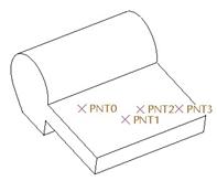
The figure at the top of the next page shows a sample sketch for these points.
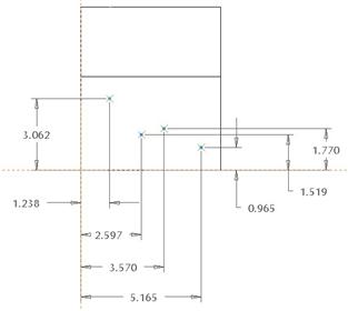
Accept the sketch once you are done, and your datum points will appear on the model, as shown in the next figure.
OFFSET COORDINATE SYSTEM
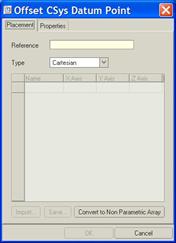
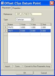
The next type of non-standard datum point creation method allows you to create multiple datum points by offsetting a coordinate system. Use Insert, Model Datum, Point, Offset Coordinate System. This brings up the following window.
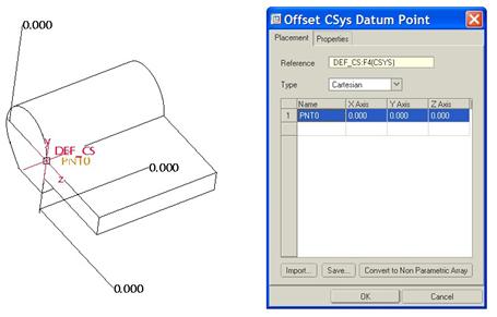
The first thing you are asked to pick is the coordinate system you are going to use. We will pick the default coordinate system DEF_CS from the model tree. Then, pick in the first row to start defining points. The window will now look like the following.
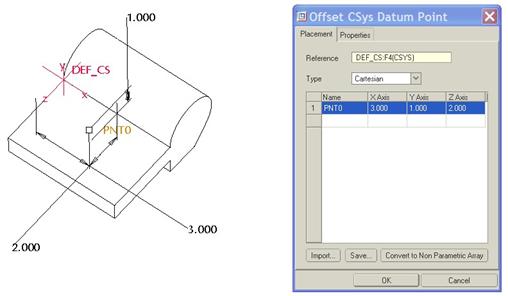
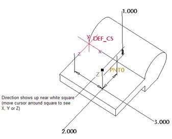
You can type in the X, Y, and Z values directly in this window. The following shows how the point moves on the model once you edit the dimension values.
You can also drag the point around the model by placing your mouse over the white square until you see the axis highlight that you are changing.
The figure at the top of the next page shows how the “Z” axis becomes visible just before you drag it.
To create another point, click in the next row in the main portion of the window. This will now look like the following.
At the bottom of this window, there are three other options. The first is used to import in a point file (has a PTS extension). The second button allows you to create a point file. If we click on this, we can save a file to our working directory. Opening the file in notepad, it looks like the following.
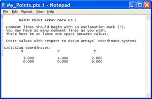
As you can see, this is a simple file to create and edit. You only need to enter X, Y, and Z values in this file.
The third button is used to remove all dimensional information from the point array. You might want to do this if you know you are not going to change these points, and you want to potentially speed up a very large point array.
DATUM AXES
Datum axes are used to create other datum features, such as planes, and they are also very useful in assembly mode to align components, set up pin constraints, etc.
To show datum axes, click on the following icon in your system toolbar.
![]()
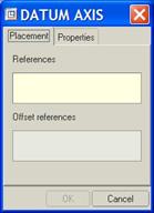
To create a datum axis, click on the datum axis icon in the datum flyout toolbar. This brings up the following window.
THROUGH EDGE
One way to create datum axes is through an existing straight edge. To create this, pick on the edge as a reference, as shown below.
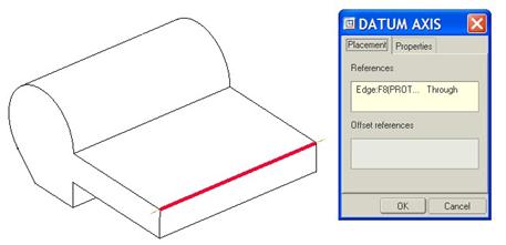
The datum axes will be created through this edge.
NORMAL TO SURFACE
If you select just a surface as a reference, you get the following window.
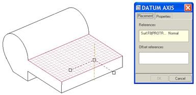
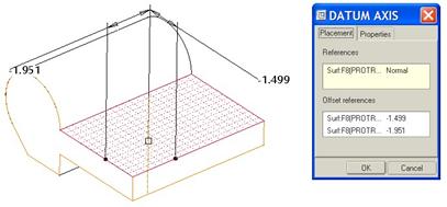
Just as we did with the “On Surface” datum point, drag the white squares to the references you wish to use to locate the point on the surface, and the axis will be created at this point, as shown below.
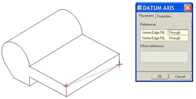
THROUGH POINTS/VERTICES
With this axes creation method, select any two vertices, datum points, or combination of them to create an axis that goes through these points, as shown below.
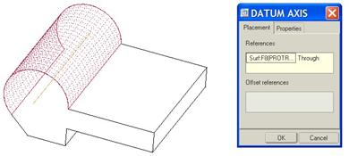
THROUGH CYLINDER
This creates a datum axes through the center axis of a revolved surface, such as a cylinder. By default, most cylindrical surfaces or revolved surfaces will already have an axis, so you may not need to create this type very often.
The following window shows the model and Datum Axis window when you pick on the cylindrical surface.
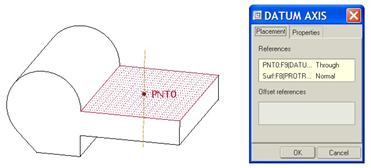
POINT NORMAL TO PLANE
With this creation type, select on a datum point, then select a planar surface that the axis will be normal to. This creates an axis normal to the selected plane passing through the datum point. No dimensions are necessary for this one.
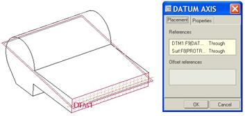
INTERSECTION OF TWO SURFACES / PLANES
This is an axis that is created where surfaces or planes meet. They must intersect to form a single straight line, otherwise the axis does not lie in a single plane, and therefore can not be created. The following window shows the intersection of the front surface and a datum plane.
DATUM COORDINATE SYSTEMS
You may need to create a datum coordinate system for some features. To show coordinate systems, click on the following icon in the system toolbar.
![]()
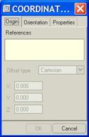
When you click on the datum coordinate system icon in the datum flyout tool, you get the following window.
The most common way to create a datum coordinate system is to pick three surfaces or planes. The following shows a coordinate system window and model when three surfaces are selected.
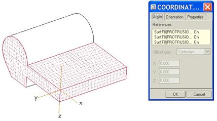
We can see that all three surfaces are highlighted and each has a constraint of “On” set. We will need to go to the Orientation tab next to define the X, Y, and Z directions. Clicking on this tab, we see the following.
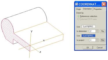
The objective in this tab is to select a surface whose normal represents the coordinate system axis. I have selected the front surface to determine the Z direction, and then selected the side surface (still highlighted) to project the X direction. I had to Flip the X-direction to get the result that you see above.
This same method works for selecting datum points and vertices as the original reference.
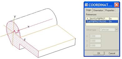
Another method for creating datum coordinate systems is to select an axis as the original reference. When we do this, it places one of the three axes along the axis that we select. We must then select at least one surface that is normal to the axis as a second reference, as shown in the following figure.
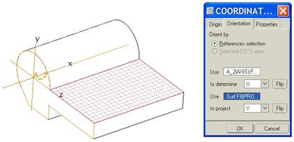
On the Orientation tab, we will select a third surface that will define the projected axis direction. Then we can set which one is X, Y, or Z. The following figure shows this tab, and the selected surface.
The last method for creating datum coordinate systems that we will cover is to offset an already existing coordinate system.
Therefore we will select the DEF_CS coordinate system as our first reference. The window will look like the following.
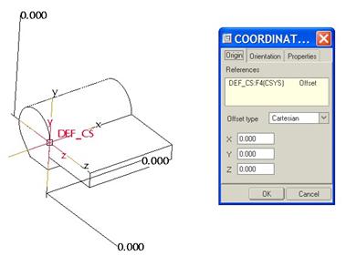
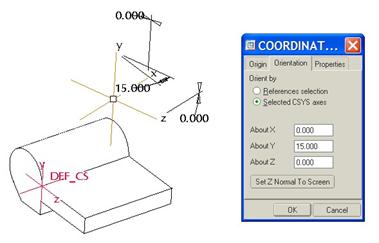
We can use the mouse to drag the white square, or enter values for X, Y, and Z offsets in the fields provide. On the second tab, we can specify its orientation by entering rotation angles in the fields, or by selecting references on the model to orient to. I have chosen to rotate the coordinate system about the Y axis (this is the Y axis of the DEF_CS coordinate system). The result is shown below.
LESSON SUMMARY
Datum features are very common in Pro/ENGINEER. You will get to know them very well. Use datum planes, axes, points, and coordinate systems to aid in the creation of other features.
EXERCISES
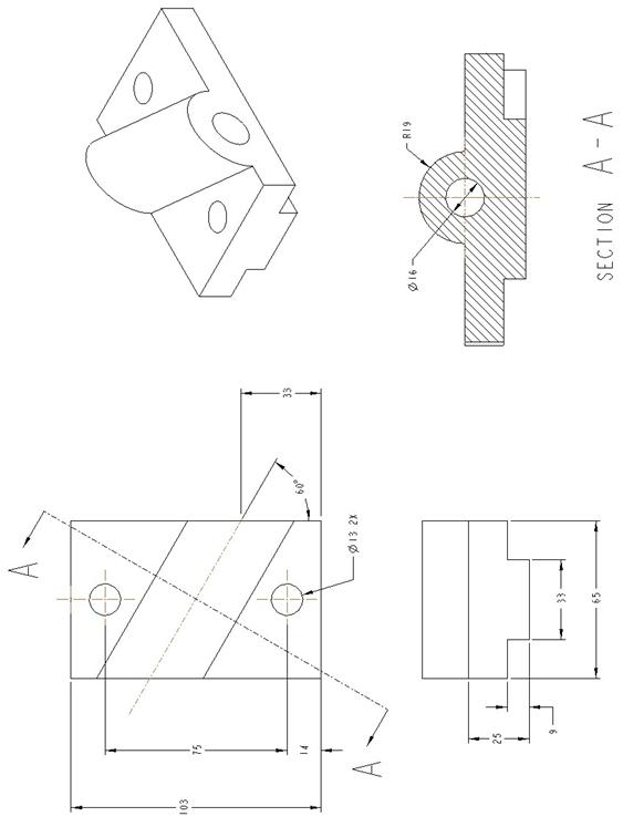
Create the following part files using the extrude feature. Create datum planes and/or axes to aid in the creation of the extrude features.
Angle_Bearing