Lesson 5

Lesson Objective: In this lesson, we will learn about the Sketch Feature. We will also learn how to start a new part.
USAGE
The Sketch feature is used to create a curve on a 2D plane or planar surface. This curve can then be used to create a variety of different features.
STARTING A NEW PART
Up to now, we have not created a part file yet. We will now create one before we can create our sketch feature. To start a new part, click on File, New, or click on the following icon.
![]()
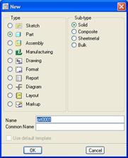
In the New window, make sure Part is selected in the first column, and Solid is selected in the sub-type column. Enter a name for the part in the field at the bottom. The window looks like the following.
Click on OK to complete this window. A new window appears as shown below.
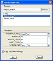
In the upper portion, we want to make sure the appropriate start part is selected in blue. In this example, we will show the Startpart_English start part. You can enter parameter values in the spaces provided at the bottom and then click on OK to continue.
The part will open in your working window. By default, datum planes should be visible, so the model looks like the following.
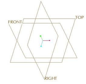
The model tree will appear in the Navigator, showing all of the existing geometry.
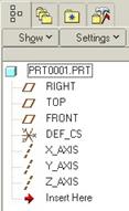
We can see that there are three datum planes, one datum coordinate system, and three datum axes in every part created from the start part. This is intentional. We will learn more about datum features in upcoming lessons. Depending on the organization, you may have different start parts with different start part geometry.
CREATING A SKETCH FEATURE
On the Feature Toolbar, you will find a fly-out icon that represents datum features. Fully expanded, it will look like the following.
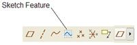
As indicated in the above figure, the Sketch feature is the icon that appears as a blue squiggly line on a dotted grid. When you pick on this feature, you are prompted to pick your sketching plane. The next section will describe the dialog box for selecting sketching planes.
SELECTING SKETCHING PLANES
For any feature where a sketch is required, you are prompted to select a sketching plane. In the Sketch feature, when prompted to pick a sketching plane, we will see the following dialog box.
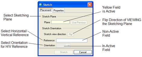
In Wildfire 2.0, dialog boxes that contain more than one field will indicate the active field by filling it yellow. In the figure above, the field used to select the sketching plane is currently filled in yellow.
A field that is white (Reference in this case) is an available field to select but is not the currently active field. To activate a “Non-Active” field, simply click once in the field with the left mouse button. Any field that is grayed out is currently “In-Active” until enough references are picked to make that filed active.
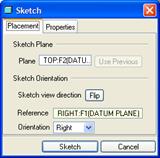
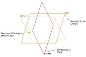
Therefore, we would start by picking on the sketching plane. In this example, we use the TOP datum plane.
Once we select this, we may see another datum plane or planar surface on the model get selected automatically as the horizontal/vertical reference, and its orientation will be selected as well. This is a good thing from a time saving standpoint, but you will want to be aware which entity is selected, and how it is facing. NOTE: There are times when it won’t automatically assume an H/V reference.
In this example, when we pick on the TOP datum plane, it automatically assumes we want to face the RIGHT datum plane towards the Right. Our window shows this in the next figure.
To change the reference entity, you can simply pick a new one on the model, because it is currently the active field. Be sure to note the orientation, as you may need to change it for the new reference. For example, if we wanted to face the FRONT datum plane towards the Bottom, we would need to first select the plane, and then change the orientation to “Bottom” in this window.
In Wildfire 2.0, the arrow is always the viewing direction in this dialog box. To change this, click on the Flip button. On the model, we can see which entities have been selected based on the color.
The sketching plane will always highlight in an orange color. The horizontal / vertical reference will always highlight in red, and the direction arrow will always be yellow. The following figure shows this.
As mentioned before, the sketch feature looks like a datum curve, but is a slightly lighter shade of blue to make it stand apart. The following figure shows the difference between a sketch feature and a datum curve (through points – which are currently not shown).
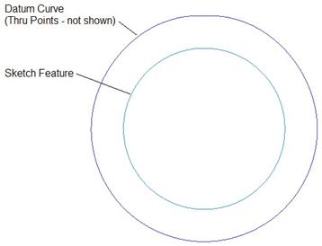
Printed out in black and white, you may not see the subtle difference, but it is there.
LESSON SUMMARY
A Sketch Feature creates a 2D curve. It can be selected directly to create certain solid features. We will see this in the next lesson.
EXERCISES
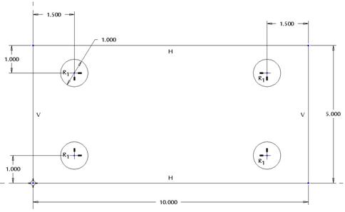
Create a brand new part called Plate_Layout. On the TOP datum plane, create the following sketch feature.
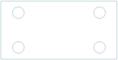
When finished, your sketch feature should look like the following from a TOP orientation.
Save and close this part. We will come back to it in the next lesson.