LESSON 15 – Draft
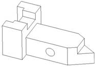
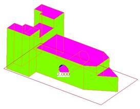
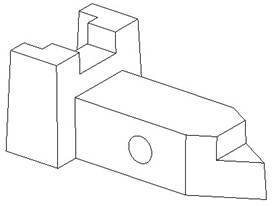
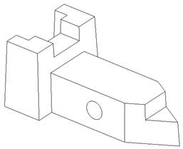
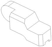
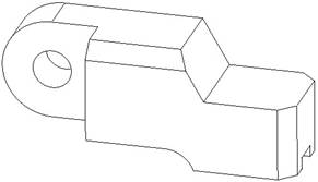
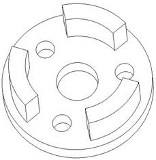
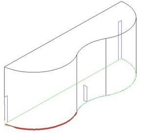
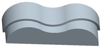
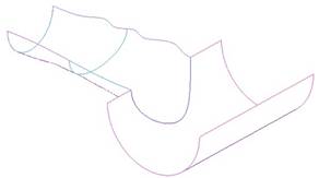
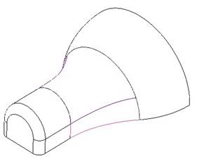
Open up the Safety_Key part that we created in Lesson 6 – Extrude. It currently looks like the following.
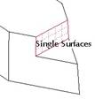
Draft Check
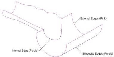
The first step to this exercise is to perform a draft check on this model to see where we need to add draft. We need at least 2 degrees of draft on all vertical surfaces. Therefore, we will go to Analysis, Geometry, Draft, which brings up the following window.
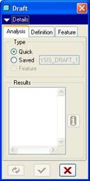
Go to the Definition tab, which looks like the following.

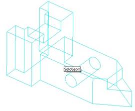
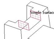
We will start by right clicking over the model until we see the entire part highlight in blue, and the tool tip says SolidGeom, as shown in the next figure.
Then, click with the left mouse button to select the entire model. In our Draft window, we should see this selection as follows.
![]()
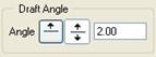
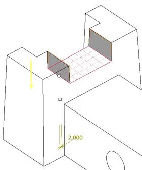
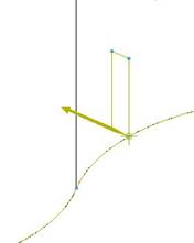
Now, we will skip over the next field, and in the Draft Angle section, click on the Both Sides button, and change the angle to 2.0, as shown in the next figure.
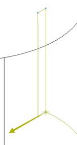
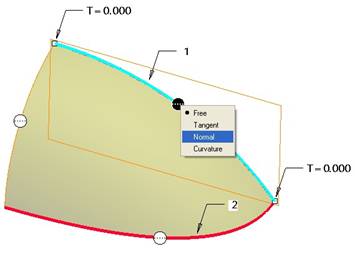
Now, go back and click on the Direction field to activate it, and select on the TOP datum plane. The model will change color, as shown in the next figure.
On the left side of our screen, a legend appears that indicates the draft angle currently assigned to each color, as we can see in the following figure.
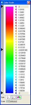
From this legend and our model, we can see that all of the vertical surfaces are shaded in green, which indicates a 0.0 degree draft. This is obviously unacceptable, so we must add draft to all of these green surfaces.
Adding Draft
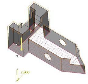
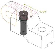
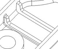
Close out of this analysis window, and click on the draft tool. For the surfaces to draft, we will use the Ctrl key to pick all of the surfaces that touch the bottom surface of the model, as shown in the next figure.
Next, click in the Draft Hinge field to activate it, and pick on the bottom surface of the model. We are using this surface, because we have been told in the exercise that the footprint of the model can not change size, therefore, it should be our draft hinge. When we do this, the preview shows the surfaces angled, and we will enter 2.0 for the draft angle. Make sure the surfaces angle into the model as they go up, as we can see in the following preview.
Click on the green check mark to complete the first draft feature, and our model will currently look like the following.
We still have three surfaces that needed draft, but these surfaces did not touch the bottom of the model, so we did not include them in the first draft feature. We will now add draft to two more of these surfaces.
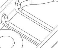
Start a new draft feature, and pick on the following two surfaces (using the Ctrl key).
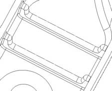
For the draft hinge, select the surface at the bottom of these two surfaces, and then enter 2.0 degrees for the draft, and make sure the draft is going into the part, as we can see in the following preview.
The model will look like the following once this draft has been completed.
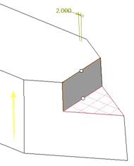
Create one more draft feature, and select the following surface to draft.
For the draft hinge, select the triangular surface that this surface touches. Enter 2.0 for the draft angle, and make sure it is going back into the part, as shown in the following preview.
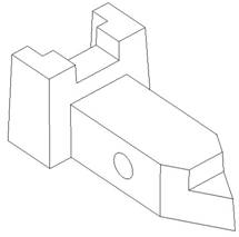
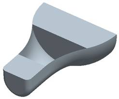
Finish this draft feature by clicking on the green check mark, and your finished model will look like the following.
Verification
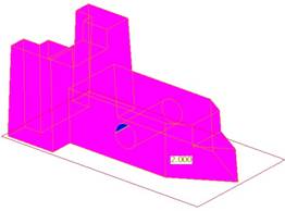
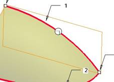
Run the draft check again using the entire model, and the same TOP plane as the direction. This time, our entire model is in magenta or blue, which indicates that we have at least 2 degrees of draft on all surfaces relative to the pull direction.
Close the analysis, and then save and close the model.
LESSON 16 – Hole Feature
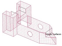
Open up the Hole_Exercise part, which looks like the following.
We are going to add three separate hole features to this model. The order does not matter.
Hole 1 – Coaxial Hole
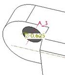
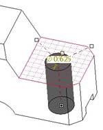
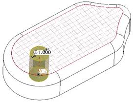
We will start with the coaxial hole at the left end of this part. To start, turn on the display of datum axes. Now, click on the hole feature. When the dashboard opens up, enter 0.625 for the diameter. Change the depth option to Through All, and now we are ready to pick references.
We will pick on the A_3 axis. When we do this, we can see the following preview.
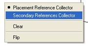
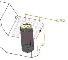
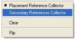
All we see is the end of the hole, but the depth part of the preview is not visible yet, indicating that we have not picked enough references. In this case, we need to define the surface that we are starting the hole from. To do this, right click out in the working window and select Secondary References Collector, as shown in the next figure.
Now, pick on the flat surface at the front of this tab that sticks out, as shown in the next figure as the meshed surface.
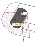
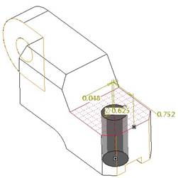
We can now see the preview for the hole in its entirety. Click on the green check mark to complete this hole, and our model looks like the following.
Hole 2 – Linear Hole
The next hole we will create will be the one on the right side of the model. Therefore, create a new hole. The diameter is the same as the one we just did (0.625), and the depth option should be set to Through All again.
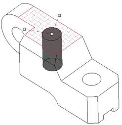
Now, pick on the flat surface indicated by the mesh below.
We can see two drag handles. We need to drag these to references to locate the hole. We will drag the first one over to the right surface of the model, as shown in the next figure.
A dimension now appears locating the hole from this surface. Now, drag the other handle over to the flat surface of the tab where we placed the coaxial hole. When we do this, we see the other dimension, as shown in the following figure.
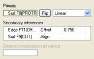
If we open up the Placement slide-up panel, we see the following.
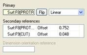
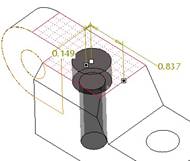
We will start by changing the first dimension value to 0.75. Next, we want to line up the hole with the tab surface, therefore, we will change the Offset type to Align, as shown in the next figure.
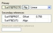
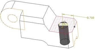
The preview for this hole now looks like the following (note the absence of the second dimension).
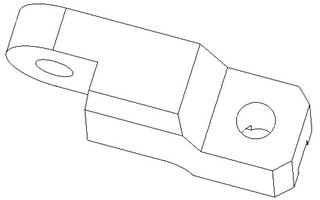
The completed hole looks like the following.
Hole 3 – Sketched Hole
The last hole will be the one in the middle. Since this hole has a counterbore profile, we will use a sketched hole to accomplish this. We could have also used a standard hole, but the dimensions wouldn’t be exactly the sizes we see here.
Therefore, click on the hole feature again. This time, we will change the hole type from Simple to Sketched. When we do this, the dashboard looks like the following.
Click on the Sketch icon, and a new window will open for the sketcher tool. Sketch a vertical centerline, and the following profile.

NOTE: Since we are sketching the depth of the hole, we should use a dimension that will go past the part. We can later set up relations to make sure that it will always go through the entire part. Since the height of the part is 1.94”, we decided to use 2.0” for this sketch.
Once you finish the sketch, you will need to pick the placement point for the hole. Pick on the top surface of the model. Drag handles appear on the simplified preview.
Drag one handle to the right edge of this surface, and the other to the flat front surface of the tabbed section, as shown in the next figure.
Now that the placement is fully defined, we can see the correct shape and size of our hole. Open up the Placement slide-up panel, and change the edge dimension to 0.75 and change the offset type to Align for the other reference, as shown in the next figure.
The preview will look like the following.
Finish this hole, and our completed model looks like the following.
Save and close this model.
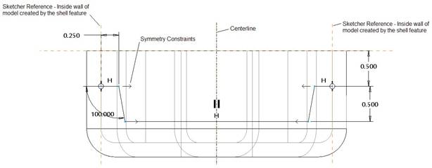
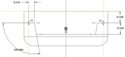
LESSON 17 – Shell Feature
Draft1
Open up the Draft1 part, which should look like the following.
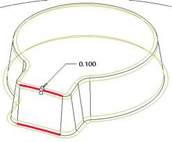
There should already be a draft of 8 degrees added to the outside of the protrusion from Lesson 15. If not, you can go back and add it before continuing. The next step is to add a 0.1 inch round to the top and bottom edge of this protrusion. We will therefore, click on the round tool, enter 0.1 for the radius value, and then pick the two edges shown below.
Once you add the round, rotate the model so you can see the large flat side of the part. Next, click on the shell tool icon from the feature toolbar, or go to Insert, Shell from the menu bar. When the dashboard appears, enter 0.0625 for the thickness, and then select the large flat side of the model, as shown in the next figure.
If you forget to pick on the surface, the shell will still be created, but no surfaces will be removed – it will be a hollow part. Click on the green check mark to finish this shell feature, which will look like the following.
Save and close this part.
Headset
Open up the headset that we have been working with. It should currently look like the following.
The first part of this exercise is to create the coaxial hole. If you recall from Lesson 16, to create a coaxial hole, we first need an axis to select. If you turn on the visibility of axes, you will see the following.
From the previous figure, we can see that we do not have any axes at the center of the cylindrical end. Therefore, we will need to create one. Click on the create axis tool, and then pick on the cylindrical surface at the end of the headset model. When we do this, we see the following.
The axis window will show Through as the placement type, as we can see in the next figure.
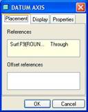
Click on OK, and our axis will be created. Now, click on the hole tool, and select this axis as the primary reference. We will see the following in our dynamic preview.
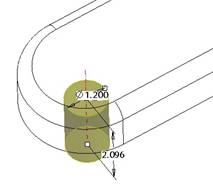
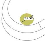
Change the diameter to 1.0, and the depth option to Through All. The preview will change to the following.
Now, right click on the window and select Secondary References Collector, as shown in the next figure.
Pick on the top, flat surface of the headset model, and you will see the following.
Click on the green check mark to complete the hole, and then rotate your model around to see the flat bottom surface, as shown in the next figure.
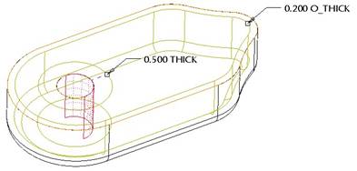
Now, we will create the shell for this model. Start by clicking on the shell tool, and enter 0.2 for the thickness. Pick on the large flat surface to remove, as shown in the following figure.
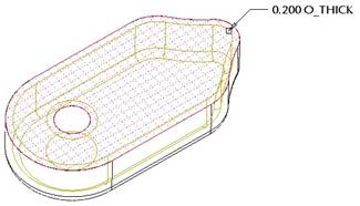
Next, click on the References slide-up panel, which looks like the following.
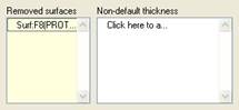
There is a field used to define non-default thicknesses. We will click in this field to turn it yellow and make it active, and then pick on one of the surfaces inside the hole (you only need to pick one). Another thickness dimension shows up on the model, and we will change its value to 0.5, as shown in the next figure.
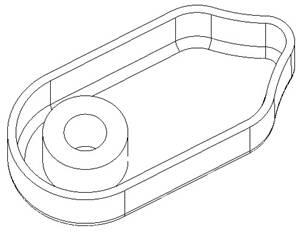
Click on the green check mark to complete this feature, and our model now looks like the following.
Save and close this model.
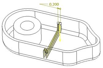
LESSON 18 – Rib Feature
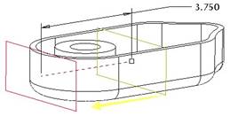
Open up the headset model once more. It should look like the last figure above. The first thing we need to do is create a datum plane to use for our rib. Therefore, click on the create datum tool, and then select on the FRONT datum plane.
Enter an offset direction of 3.75 into the model, but keep the positive side of the datum plane (indicated by the yellow arrow), going back towards the FRONT datum plane.
The following preview shows this plane being created.
Once you finish creating this plane, we are going to use it to create the rib. Therefore, click on the rib tool, or go to Insert, Rib, from the menu bar, and then right click on the screen to select Define Internal Sketch. For the sketching plane, select on the datum plane that we just created. Accept the viewing direction as going away from the hole, and accept the RIGHT datum plane facing towards the Left.
Click on the Sketch button, and sketch the following profile.
NOTE: Switch over to a hidden line view so you can see the internal edges, and select the two vertical internal edges near the outsides as sketcher references, as shown in the figure above. The sketch is symmetric about the center, and consists of five lines, as we can see if we go to a no hidden view.
Complete the sketch by clicking on the blue check mark. An arrow appears showing the material side for the rib, and it may be sticking up, which is in the wrong direction. Click on the yellow arrow if this is the case to reverse it to pointing down. We should now see the dynamic preview for the rib. Enter 0.2 for the thickness, and our preview looks like the following.
Click on the green check mark to complete the rib, which looks like the following figure.
Now, we will add the rounds to this rib. First, create a round feature using a 0.125 radius value, and pick on the following references.
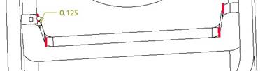
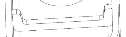
Finish this round, and it will look like the following.
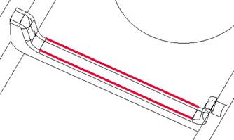
The next round will be a full round that uses the following two references.
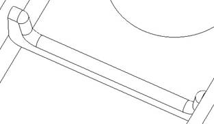
The completed round will look like the following.
The final round will be the 0.05” round that goes around the entire rib. Therefore, create a new round, enter 0.05 for the radius, and then pick on the following reference.
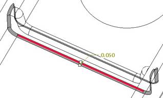
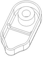
The completed rib with all of its rounds is shown in the next figure.
Save and close this model for the next lesson.
LESSON 19 – Patterns
Open up the headset again. Right now, we have a single rib completed. We are going to pattern this rib, along with the rounds that are tied to it.
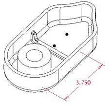
If you recall from the previous exercise, we created a datum plane that gave us our offset distance of 3.75”. Therefore, we will need to pattern this datum plane first, and then reference pattern the rib and all of the rounds. All said, we will create five individual patterns.
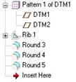
Pattern 1 – Datum Plane
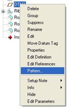
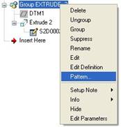
In the model tree, find the datum plane that we created for the rib (DTM1 in my example). Right click on this datum plane, and select Pattern, as shown in the next figure.
The 3.75” dimension appears on the model, as shown in the next figure.
Click on this dimension, and if the field appears, type in 1.25 for the increment. If the field does not appear, you can click on the Dimensions slide-up panel, and enter the increment in the space provided, as shown below.
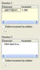
Once you enter the increment value, two black dots appear on the model, showing where the two pattern instances (including the original) will be created, as we can see in the following figure.
Click on the green check mark to create the pattern, and you will see the following.
Pattern 2 – Rib
The next pattern will be the rib itself. Right click on this rib from the model tree, and select Pattern, just as we did for the plane. When the dashboard appears, you should see Reference as the default option in the bottom, as we can see in the next figure.
![]()
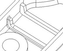
Click on the green check mark, and the rib will be patterned, as shown in the next figure.
Pattern 3 – Round
When we right click on the first round and select Pattern, it automatically patterns it for us. We won’t even get a dashboard. The following figure shows us the result.
Pattern 4 & 5 – Rounds
We will repeat this process for the remaining two rounds, as shown in the next figures.
Save and close this model.
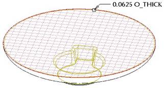
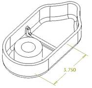
Cup_Washer
For this lesson, we are going to create two patterns, one for the protrusion that sticks up above the part, and one for the three small holes.
We will start by creating the extruded cylinder with the large hole.
Feature 1 – Extrude
Create an extrude feature using the TOP datum plane as the sketching plane, and face the RIGHT plane towards the Right. Sketch the following two circles.
Extrude this section 0.56” to create the following.
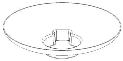
Feature 2 – Extrude
The next feature will be one of the protrusions that sticks up on the part. Note the dimensioning for this feature goes from the bottom of the part, so we will need to use the TOP datum plane for the sketching plane.
For the reference plane, we will need to create one on the fly. Therefore, after you pick the TOP plane for a sketching plane, move your window out of the way, and click on the create datum plane tool. For the datum plane creation, click on the Z_Axis going through the center of the hole. Hold down the Ctrl key, and pick on the RIGHT datum plane. Use 45 degrees for the offset angle. Our preview for the plane looks like the following.
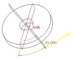
Allow the positive side (yellow arrow) to face towards the right. When you click on OK to complete this plane, you are returned to the section window. We must pick on the newly created datum plane to make it the reference, and face it towards the Right. When you click on the sketch icon, you will want to pick Z_Axis and DTM1 (newly created plane) as the sketching references.
Do NOT pick any other planes in the model as sketching references, because they are fixed and may affect our ability to pattern this protrusion later. Sketch a vertical centerline on top of our plane, and create the following symmetric profile (two arcs and two lines).
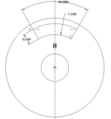
NOTE: The perpendicular constraints allow the lines on the side to understand that they go to the center of the part, because our two sketched arcs use the Z_Axis as their centers.
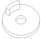
Extrude this section to a depth of 1.75, and our finished extrude feature looks like the following.
In the model tree, we can see a group created for this extrude.
It is a group, because we created the datum plane in the middle of defining the extrude feature, so it becomes grouped with the extrude, and automatically hidden.
Feature 3 – Pattern
Now, we will right click on the entire group itself, and select Pattern, as shown in the next figure.
All of the dimensions will show up on the screen. If you only tried to pattern the extrude feature itself, you would not see the driving angular dimension tied to the datum plane, as shown in the next figure.
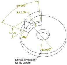
When you click on the 45 degree dimension, enter 120 for the increment, and change the number of instances to 3. Click on the green check mark, and the pattern will be created.
NOTE: The first extrude in the pattern is currently 45 degrees from the center. For this model, we want the lead extrude to be sitting at 0 degrees, so you will need to edit the first group in the pattern list (when expanded) and change the 45 degree dimension to 0.0, and regenerate the model. From a top view, the completed pattern looks like the following.

Feature 4 – Hole
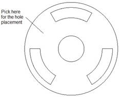
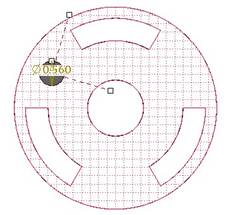
For the first hole, we are going to use an actual hole feature. Click on the hole feature, and pick on the following location.
When the preview for the hole appears, enter 0.56 for the diameter of the hole, and change the depth to Through All. The preview should now look like the following.
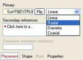
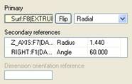
Down in the dashboard, click on the Placement slide-up panel, and change the placement type from Linear to Radial, as shown in the next figure.
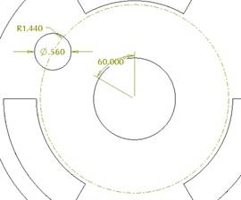
Once we do this, we will need to drag the two drag handles over to an axis and a plane. We will start by dragging one of the handles over to the Z_AXIS axis. When we do this, a radial dimension appears, and we will change its value to 1.44, as shown in the next figure.
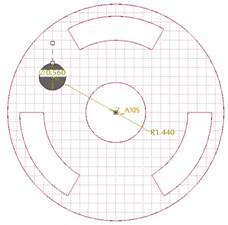
Next, drag the other handle over to the RIGHT datum plane. When we do this, an angle appears, and we will change it to 60.0 degrees, as shown in the next figure.
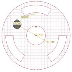
The Placement slide-up panel for our feature looks like the following.
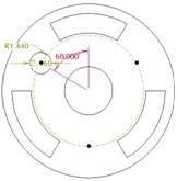
Click on the green check mark to complete this first hole, which looks like the following.
Feature 5 – Hole Pattern
The last feature for this model will be to pattern the newly created hole. Right click on the hole, and select Pattern from the model tree. The dimensions show up on the model.
We will pick on the 60.0 degree dimension, and enter an increment of 120 degrees. Change the number of instances to 3. Unlike the group pattern that we did previously, this pattern will show the black dots indicating the location of the patterned instances, as shown in the next figure.
Click on the green check mark to complete this pattern, and our finished model will look like the following.
Save and close this model.
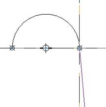
LESSON 20 – Variable Section Sweeps
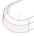
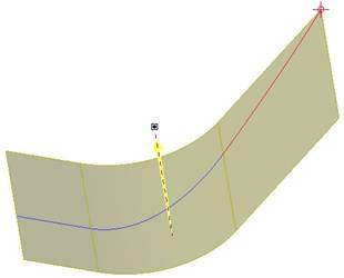
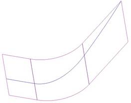
Open up the Basket part that we created earlier. It should look like the following.
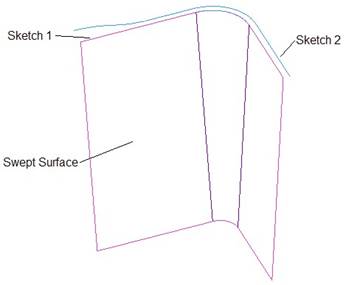
We are going to use Sketch 1 and Sketch 2 to create a new surface that has a semi-circular profile all along its length, but the radius of the semi-circle will be dependent on the outer trajectories used.
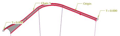
Therefore, we will click on the Variable Section Sweep tool, or use Insert, Variable Section Sweep from the menu bar. When the dashboard appears, select Sketch 1 on the model. Make sure the entire curve is highlighted before you select it.
Once you select it, your model should look like the following.
The yellow arrow indicates the start of the trajectory, and should be located where shown above. If not, click on the yellow arrow to flip it to the other end. Now, hold down the Ctrl key, and select the entire Sketch 2 curve, as shown in the next figure.
Now that both trajectories are selected, we will click on the sketch icon in the dashboard. NOTE: By default, the surface option is selected, which is what we want for this model.
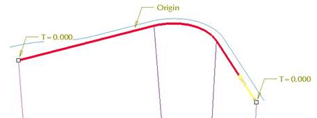
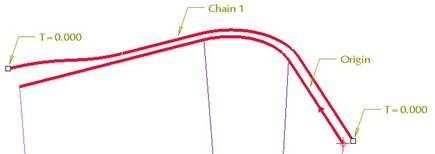
When we click on the sketch icon, we are placed into the section, looking at the two ends of the trajectories that we selected. These ends are indicated by the “X” symbols in the sketch. We want to sketch a semi-circle using these two “Xs” for the arc ends, as shown in the next figure.
When we finish the sketch, we should see the following dynamic preview.
We can see the semi-circular shape all along the trajectories, but increasing in size at the other end. Click on the green check mark to complete this feature. Our basket now looks like the following.
Save and close this part.
LESSON 21 – Swept Blends
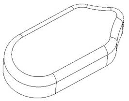
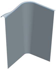
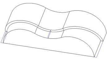
Open up the Swept_Blend2 part. It looks like the following.
We can see three individual rectangular sketches. Each of these shares the outside edge of the model, which we can use as a trajectory.
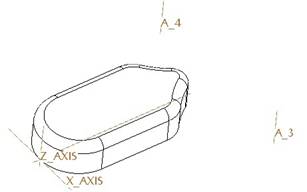
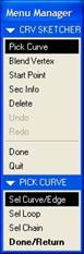
We will go to Insert, Swept Blend, Cut from the menu bar, and the following menu manager appears.
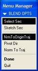
We will select the Select Sec option (as shown above), because we are going to select the sections. We will leave the Normal to Origin Trajectory (NrmToOriginTraj) option selected. Click on Done to continue.
This brings up the following window.
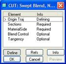
The menu manager gives us the following choices.

We will select the front edge of the model, therefore, select the Select Traj option. When we pick this option, we get the following menu manager.
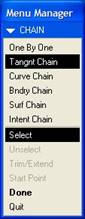
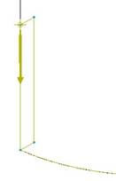
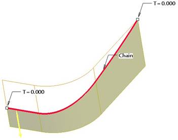
We want to pick on the entire tangent set of front edges, therefore, we will pick on the Tangent Chain option, and pick the first arc indicated by the bold red selection in the next figure.
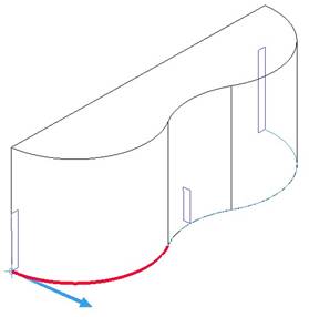
An arrow appears, indicating the start of the trajectory. We will leave it in the location shown. The entire edge should be highlighted in blue, showing the full tangent chain of edges. Click on Done to continue. A surface should highlight in green. Click on Accept if it is the bottom surface of the part, as shown in the next figure. If not, click on Next until you see this surface highlight, and then click on Accept.
We are placed into the menu to select the sections, which looks like the following.
We will use the Sel Loop option to select the entire loop of edges that make up the rectangle in our section. Once we pick this option, pick on one of the lines of the rectangle sketch that sits at the beginning of our trajectory. When we do this, an arrow appears on one of the vertices, as shown in the next figure.
In order to avoid a twisting effect, we want the vertex for each section to be the same one. For consistency, we want to use the vertex that sits on the trajectory. Therefore, click on Start Point in the menu manager, and select on the vertex that lies on the trajectory, as shown in the next figure.
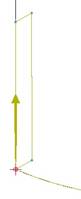
The arrow now appears on this vertex. Do not worry about the direction of the arrow. Click on Done to move on to the next section.
Use the Sel Loop option again, and pick on the small rectangle in the center of the model. Make sure the start point is sitting on the vertex that lies on the trajectory, as shown in the next figure.
Click on Done to continue. In the message bar, we are prompted to create another section. Click on Yes to create one more section.
Repeat the same process to pick the last section (Sel Loop). Make sure the start point is in the correct spot, as shown in the next figure.
Click on Done. In the message bar, enter No to finish creating sections. An arrow appears on the model indicating direction of material removal, as shown in the next figure.
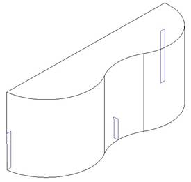
We want to click on Flip, followed by Okay to get the material to remove inside the rectangle. Click on OK to complete this feature, which looks like the following.
If you hide the three sketched rectangles and shade the part, it will look like the following.
Save and close this model.
LESSON 22 – Boundary Blended Surface
Open the Boundary4 part. It looks like the following.
We can clearly see the seam lines in this model, due to poorly defined boundary conditions. We will fix this by editing the definition for the MAIN_SURFACE feature in the model tree. When we use Edit Definition on this feature, we see the following.
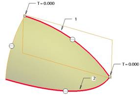
Right now, we can see that all boundary edges have a Free state associated with them. Because we are going to be mirroring this surface about two planes, we want to make sure that our edges on those planes have a Normal condition applied to them, as indicated in the next figure.
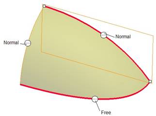
We will start by right-clicking on one of the boundary condition symbols and select Normal, as shown in the next figure.
When we do this, the boundary condition symbol changes to the appropriate condition, as we can see in the next figure.
We will do the same thing to the next boundary condition, as we can see in the following figure.

Its resulting condition will look like the following.
When we click on the green check mark to complete these changes, the rest of the features resume, and our finished surface model will look like the following.
We can now see that the seam lines are gone. Save and close this model.
LESSON 23 – Copy & Paste Tool
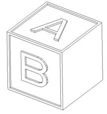
Open up the model entitled Toy_Block, which currently looks like the following.
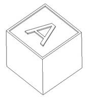
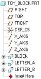
In the model tree, we have a feature called Letter_A, which is an extruded cut that creates the letter. We are going to copy this feature to create the rest of the letters.
For the purpose of saving space, we will only demonstrate how to do this with the letter “B”, but you can continue to create the rest of the letters (C-F).
The first thing we will do is highlight Letter_A in the model tree, and then go to Edit, Copy from the menu bar. Once we do this, select Edit, Paste from the menu bar, which will bring us into the dashboard for an Extrude feature. We will notice in our dashboard, that the remove material icon is already selected, as it should be.
We will need to edit the placement of the sketch, and possibly tweak the sketch itself. Therefore, right click on the working window, and select Edit Internal Sketch, which brings up the section window, as shown below.
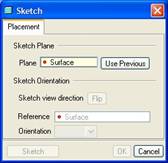
We can see that we must re-select our sketching plane and sketching reference plane. For the sketching plane, we will pick on the front side of the block where we currently see the “B” letter in our exercise. We will face the RIGHT datum plane towards the Right.
When you are placed into the sketch, you can see an outline of the current sketch floating along with your mouse, as shown in the next figure.
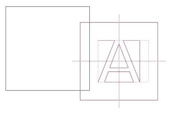
We want to move our mouse so the letter appears like the following (approximately centered on the block face).

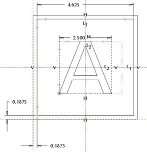
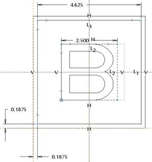
Click once to place the sketch. The dimensions will appear, and we want to make sure we have two locating dimensions, each modified to 0.1875”, as shown in the next figure.
Next, pick on the letter “A”, and then click on the Modify icon. This will bring up the following window.
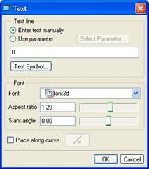
Change the text to “B”, and then you can adjust any other settings as necessary to get the letter looking like you want it. Click on OK once you are happy with your letter, and your sketch will look like the following.
You could further change your letter by modifying the 2.5” dimension. We will leave it alone, and click on the blue check mark to finish this sketch. We are placed back into the section window, where we will click on OK.
Finally, click on the green check mark to complete this feature, and we can now see our finished letter “B”, as shown in the next figure.
On the model tree, we should see an Extrude 1 feature. We want to rename this to LETTER_B, as shown in the next figure.
Save and close your model.
LESSON 24 – Fill Tool
There are no exercises for this lesson.
LESSON 25 – Merge Tool
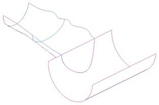
Open up the model entitled Project_Exercise, which looks like the following (no hidden mode):
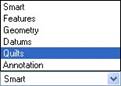
The goal for this exercise is to merge the two surfaces together to make a single quilt surface. When selecting surfaces, it is easier to change your selection filter to Quilts, as shown in the next figure.
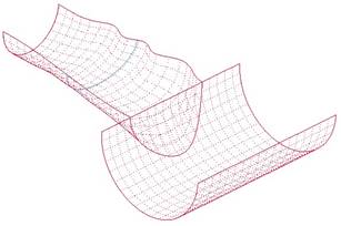
Then, select one of the surfaces, hold down the Ctrl key, and then select the second surface. Both surfaces will mesh in no hidden mode, as shown in the next figure.
Once both surfaces are selected, the merge tool is available. Click on this tool, and we will see the following preview.
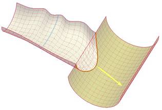
Both surfaces highlight in a yellowish hue. The first surface that you pick (considered to be the parent surface) is more of a yellow color, while the second surface you selected (considered the child) is more of a cream color.
A yellow arrow will indicate which side of the quilt(s) will be kept after the merge. We want it to look like the figure above. If it does not, you will need to click on the yellow arrow to flip the material side. Once it looks like the figure above, click on the check mark to complete the merge. The model will now look like the following.
We can see that the top edge of the cylindrical surface has been removed within the adjoining curve. If we hide the project feature and the sketch features in the model, we get a clear picture that these two surfaces are indeed merged, because we can see a purple internal edge between the two surfaces, as shown in the next figure.
Save and close this model.
LESSON 26 – Trim Tool
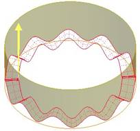
Open up the Indexing_Surface model. It will look like the following figure.

We are going to use the indexing surface (the wavy one) as a trimming tool to cut out the bottom of the cylinder, thus retaining the indexing edge. Unlike the merge, which would have kept the index surface, we only want to have the cylinder when we are done, therefore, a trim is a better tool.
We will start by going to our Quilts selection filter, and the pick on the cylindrical surface, as shown in the next figure.
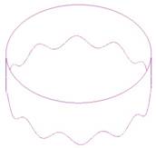
Once you have the cylinder selected, click on the trim tool. When the trim dashboard appears, select on the indexing surface. We will see the following.
From this preview, we can see that we will be getting rid of the top of the cylinder, and only keeping the bottom portion, under the indexing surface. This is not what we want, therefore, click on the yellow arrow to flip the material side, and you will see the following.
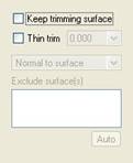
This is exactly what we want, but before we finish the model, we need to remove the trimming quilt. To do this, click on the Options slide-up panel, and uncheck the Keep Trimming Surface option, as shown in the next figure.
Now, click on the green check mark to complete this feature. Our model now looks like the following.
Save and close this model.
LESSON 27 – Intersect Tool
Open up the Intersect_Ex part, which looks like the following. NOTE: Datum planes have been turned off to view these sketches easier.

To be able to create this model, we are going to need to do a combination of three things.
Feature 1 – Intersect Curves
Be sure your selection filter is not on Quilts anymore. Select one of the two sketches, then hold down the Ctrl key, and select the other. Once both are selected, click on the Intersect tool. This will create the following curve at the projected intersection of both curves.

The original two sketches are automatically hidden in the model tree. That is okay – because for our next feature, we can pick the first sketch directly in the model tree.
Feature 2 – Extruded Surface
In the model tree, select Sketch 1, and then click on the Extrude tool. When we do this, the dynamic preview shows a surface, as shown in the next figure.
For the depth of the surface, change to the To Selected option, and pick on the upper end of the curve, as shown in the next figure.
Click on the green check mark to complete this surface, which looks like the following.
Now, we can use the intersected curve as a trimming tool on the surface. Therefore, pick once on the surface to select it (or select it from the model tree), and then click on the trim tool.
Once the trim dashboard appears, click on the curve. A preview will show which side of the surface will be kept. Flip the arrow if necessary to arrive at the following preview.
Click on the green check mark to complete this trim, and your finished surface will look like the following.
Save and close this model.
LESSON 28 – Offset Tool
There are no exercises for this lesson.
LESSON 29 – Solidify Tool
Open up the BBS1 model, which will look like the following.
We want to take the middle of this part (which is a surface) and turn it into a solid. If we rotate and shade the model, we can see that the surface is not closed, as shown in the next figure.
Therefore, the first thing we need to do is to create a Fill surface. Click on the Fill tool, or go to Edit, Fill, and when the dashboard appears, right click in the working window and select Edit Internal Sketch.
For the sketching plane, select the TOP datum plane. Face the RIGHT plane towards the Right, and then use the Use Edge tool to get the two sides of the surface, as well as the two solid edges that close off the boundary, as shown in the next figure.