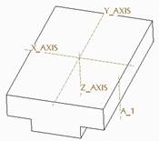
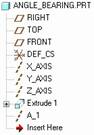
We can see our new axis, as well as the three default axes in the start part. We will turn off the display of axes, because we will be able to pick from the model tree, which looks like the following.
Datum 2 – Datum Plane
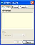
Now, we will create our first datum plane. Therefore, click on the datum plane tool, or select Insert, Model Datum, Plane from the menu bar. This brings up the following window.
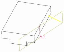
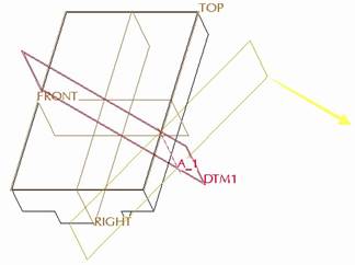
We will start by picking on the A_1 axis from the model tree. The dynamic preview shows a plane going through this axis, and it is at an angle, as shown in the next figure.
Now, hold down the Ctrl key, and select the side surface that the axis goes through. When we do this, an angle appears on the dynamic preview and the datum plane rotates, as shown below.
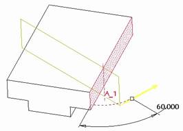
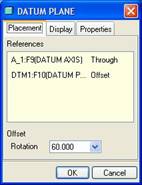
Change the angle to 60.0 as shown in the previous figure, and then our window will look like the following.
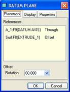
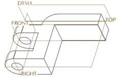
You may notice that the yellow arrow is facing to the back side of the datum plane (as viewed from a default orientation). We want this to be this way, so if you accidentally flip the arrow to the front, flip it back to the back by clicking on it. Click on OK to finish this datum plane, and then turn on the display of datums to see the result.
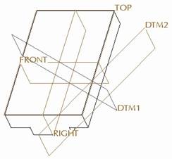
We should be able to see the black side of the DTM1 datum plane in a default orientation, as shown in the previous figure.
Datum 3 – Datum Plane
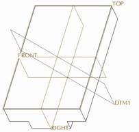
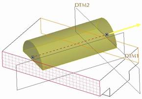
Our last datum plane will be our eventual sketching plane. To create this, go back to the datum tool, and for our references, we will select the A_1 axis, followed by DTM1 (using the Ctrl key). When we do this, we will see the following.
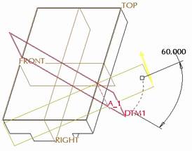
Currently, our datum plane window looks like the following.
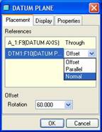
We could change the angle to 90 degrees, but instead, we will go to the datum plane window, and change the second reference type from Offset to Normal, as shown in the next figure.
Next, click on the Display tab in the window. It currently looks like the following figure.
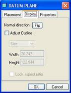
We will flip the direction for the positive side of the datum plane. We could have picked on the yellow arrow on the model itself, or click on the Flip button from this tab. Once we do this, we see the following.
Click on OK to complete this datum plane, which now looks like the following.
We can see the positive brown side of DTM2 facing towards the front right, as shown in the previous figure. We are now ready to continue with solid features.
Extrude 2 – Cylindrical Protrusion
Create another extrude feature. Use an internal sketch, and select the DTM2 datum plane as the sketching plane. Use DTM1 as the reference, facing towards the Right. Inside the sketch, create the following.
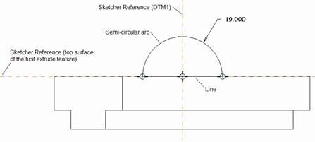
NOTE: We can’t create the hole at the same time, because we can’t remove material and add at the same time. Also, you will have to select sketcher references for this model, because the system doesn’t automatically select them.
Click on the blue check mark to complete this sketch, and your dynamic preview will look like the following.
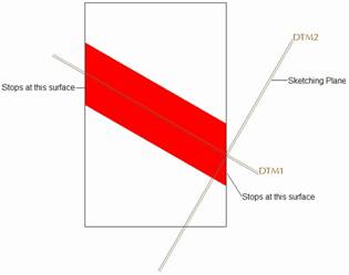
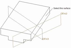
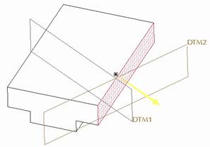
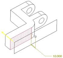
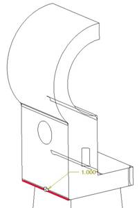
Here is the other tricky part about this problem. Since our sketching plane rests at the edge of our model, we actually need to have geometry created in two directions. The following figure shows the area that needs to be created (shaded in red).
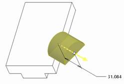
As we can see from the previous figure, we have to stop the protrusion at the two side surfaces, therefore, we will change our depth option to “To Selected” (the one with the red in it), and select the surface shown in the next figure.
When we do this, we see the following dynamic preview.
We are not done yet. Using the Options slide-up panel, set the depth in the second direction to “To Selected” as well.
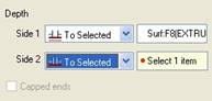
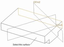
For the second direction reference, pick on the opposite surface, shown in the next figure.
Our dynamic preview now looks like the following.
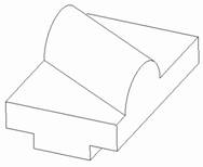
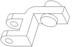
Click on the green check mark to complete this extrude feature, which now looks like the following.
Extrude 3 (Cut) – Axial Hole through top Cylindrical Protrusion
To create the hole that goes through the cylindrical protrusion that we just created, we will use the same sketching plane, reference plane, orientation, and sketcher references, but this time our sketch will look like the following.
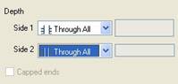
When you complete the sketch, be sure that you have selected the Remove Material option, and change the depth option to Through All for both directions, as shown in the next figure.
Our dynamic preview should look like the following.
Click on the green check mark to finish this extruded cut, which now looks like the following.

Extrude 4 – Final cuts
For our last feature in this model, we will create another extruded cut, and use the TOP datum plane for the sketching plane. Be sure the arrow for viewing is going into the part, and then use the RIGHT datum plane to face towards the Right.
Inside sketch mode, sketch the following.
When finished sketching, change the depth option to Through All, and our dynamic preview will look like the following.
Click on the green check mark to complete this extrude feature. Our final model looks like the following.
Save and close this model.
LESSON 9 – Revolve Feature
Create a new part called Bearing2.
Revolve 1 – Body of the Bearing
For our first feature, we will click on the revolve icon. Use an internal sketch, and select the RIGHT datum plane for our sketching plane, and then use the TOP datum plane to face towards the Top.
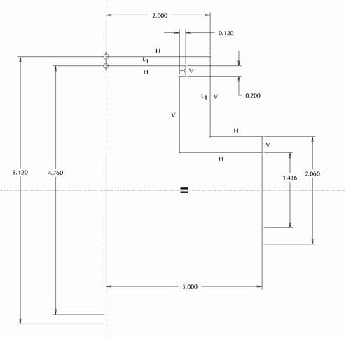
Inside the sketch, start off with a horizontal centerline on the existing horizontal sketcher reference, and then sketch the following profile. NOTE: Many of the dimensions are diameters, even though we only sketched half a model. The way you create this type of dimension is to select on the line/vertex followed by the centerline, and then select the same line/vertex again. When you place the dimension with the middle mouse button, a diameter dimension (or symmetric dimension) appears on the sketch.
Click on the blue check mark to complete the sketch. Our dynamic preview looks like the following.
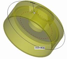
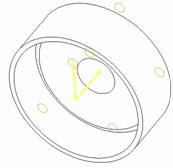
Click on the green check mark to complete this revolve feature, and then you will have the following.
Extrude 1 – Holes
The last feature for this bearing is the set of holes in the center of the bearing. We will click on the extrude tool, followed by the Remove Material option.
For the sketching plane, use the FRONT datum plane, and face the RIGHT datum plane towards the Right. Sketch the following.
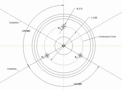
NOTE: To make the construction circle, sketch a regular circle, select it, and then right click and select Construction.
When finished, our dynamic preview (with a depth option of Through All) looks like the following.
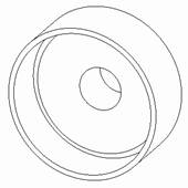
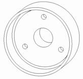
The final model will look like the following once you finish this extruded cut.
Save and close this model.
LESSON 10 – Datums Part 2
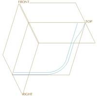
Create a new part called Basket. In this exercise, we are asked to create two sketched curves. We can do this with the sketch feature that we learned about in Lesson 5. These curves are going to be used later as trajectories to create the main body of the basket part.
Sketch 1
Click on the sketch feature, or go to Insert, Model Datum, Sketch. For the sketching plane, select the TOP datum plane, and face the RIGHT datum plane towards the Right. For the first sketch, it will be easier to start with the internal curve.
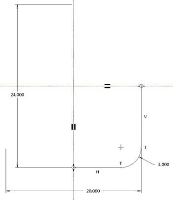
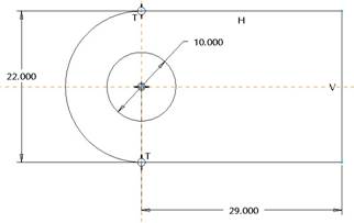
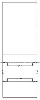
Therefore, we will sketch the following profile, which consists of two centerlines, two lines and an arc.
The finished sketch feature will look like the following.
NOTE: Be sure to use symmetrical dimensions as indicated in the figure. Therefore, you will need two centerlines in this sketch.
Sketch 2
The next sketch will complete the outside curve. For sketcher references, be sure to pick all three entities from the first sketch that we made, and then sketch in the order starting with Line 1 in the following figure.
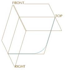
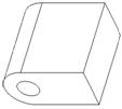
This completed sketch (and part) will look like the following.
Save and close this part for a later lesson.
LESSON 11 – Sweep Feature
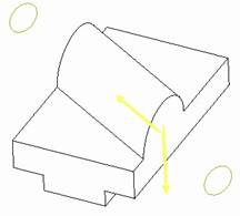
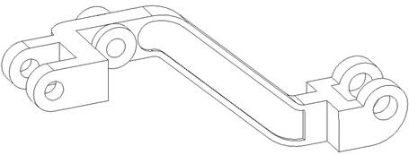
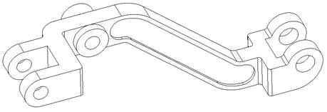
Dash_Pot_Lifter
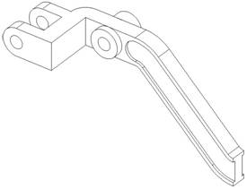
This is (admittedly) the most difficult exercise, but the actual definition of the model is not difficult once you see the solution. It just seems overwhelming, because you may not know where to get started.
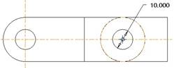
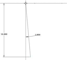
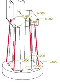
If we take a look at the exercise figure, and pay close attention to the dimensions, we can see that there is a progression that must exist. For example, in the FRONT view, we see a hole-to-hole dimension of 140 mm. In order to be able to do this, we have to have the hole on the left, but to have the hole on the left, we have to have the farthest hole on the left side of the part.
Therefore, we will need to work from left to right on the part. To do this part, we are going to use a combination of Datum, Extrude, Revolve and Swept features. Start by creating a new part called Dash_Pot_Lifter, and use a metric start part (if available).
Feature 1 – Extrude
The first feature we will create is an extrude. Use the FRONT datum plane as the sketching plane, and face the RIGHT plane towards the Right. We will sketch the following profile.
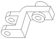
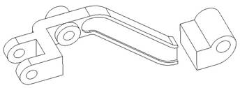
Extrude this feature to a depth of 38 mm. The first feature will look like the following in a default orientation.
Feature 2 – Extrude (Cut)
The next feature will be an extrude that cuts out material from this first feature. For the sketching plane, use the TOP datum plane, and face the RIGHT datum plane towards the Right. Sketch the following rectangle.
For the depth option, go Through All in both directions (using the Options slide-up panel). The finished extrude will look like the following.
Feature 3 – Extrude
The next feature will be an extruded protrusion. The sketching plane will be the top flat surface of the first extrude. Be sure the viewing direction is going into the part. Face the RIGHT datum plane towards the Right. Inside the sketch, use the right surface as a sketcher reference, and sketch the following.

When you finish the sketch, be sure the feature is going in the right direction, and flip it if it is not. Use the To Selected depth, and pick the opposite surface of the first extrude feature, and the completed feature looks like the following.
Feature 4 – Datum Plane
If we look at the first cylindrical protrusion in the part, we can see that the back side of the cylinder sits 10mm away from the main body of the part, but the overall length of the cylinder (27mm) is based on this same reference point. Therefore, we should create a datum plane 10mm offset from the back side of the part.
Therefore, click on the create datum plane icon (or use Insert, Model Datum, Plane), and pick on the following reference.
When the preview for the plane appears, change the offset distance to 10, and flip the positive side of the datum plane so it faces into the part, as shown in the next figure.
The reason we flipped the positive side, is so we can see the brown side when we are in a default orientation, as shown in the next figure for the completed datum plane.
Feature 5 – Extrude
The next feature will be the cylindrical protrusion that extrudes from the DTM1 plane up 27mm into the part. Therefore, use DTM1 as the sketching plane, and make sure the viewing direction is facing away from the part. Use the flat, topmost surface of the part as the reference surface, and face it towards the Top.
Add the TOP datum plane as a sketcher reference in addition to the RIGHT plane and the top flat surface of the part (which should already be selected as references). Sketch a circle centered on the TOP datum plane reference, tangent to the top surface sketcher reference, as shown in the following figure.
Extrude this circle into the part a distance of 27mm to create the following.
Feature 6 – Extrude (Cut)
Even though we could do this next feature any time in the model, we will do it now, since we are working left to right. Therefore, we will create another extrude, and use the front flat surface of the cylindrical protrusion we just created, and face the TOP datum plane towards the Top. For a sketcher reference, add at least one of the circular edges of the cylinder that we just created, and sketch a circle, as shown in the next figure.
Extrude Through All to get the following.
Now might be a good time to save this part if you haven’t already.
Feature 7 – Revolve (Cut)
This next feature is one that can be done several different ways. If you look at the cross-section “A” through the bend in the part, we can see an “I” profile. We can always add this “I” in later as an extruded cut on each side, but because we have a width of 8mm for the middle of the “I” we might want to do it a different way to preserve the dimensioning intent of this exercise.
Therefore, we will create the half-circle portion of the cut out by using a revolved cut. Click on the revolve tool, and the remove material icon. For the sketching plane, use the small rectangular surface at the right of our model. Face the TOP datum plane towards the Top.
When we get into sketch mode, select the right edge of the rectangle as a sketching reference (the left side should be covered by the FRONT datum plane already), and be sure to sketch a horizontal centerline on the TOP sketcher reference.
Then, sketch two rectangles on the top half of the centerline, and dimension according to the following figure.
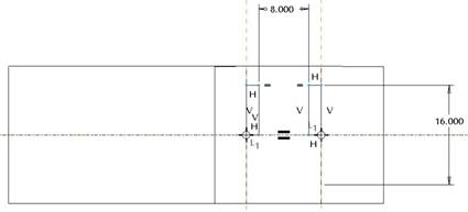
For the depth option, accept the default of 360 degrees. NOTE: You could use 180 and make sure it is inside the part. The reason for using 360 at this time, is because there is no geometry outside of the model to the right that we are worried about cutting, and we want to make sure we completely cut through the right side of the part. Depending on part accuracy, we could end up with a very small surface with 180. The final revolve feature looks like the following.
If you rotate the model, you will see the semi-circle on both sides of the part, forming the “I” profile at the end. We could have done this with extruded cuts, but would have had to make two separate cuts to do what we did in one revolve cut.
Feature 8 – Sweep
We are finally ready to perform our sweep operation (the whole point of this exercise). The good news is that we have already prepared our sweep profile (the “I” beam shape), all we need to do is define the appropriate trajectory.
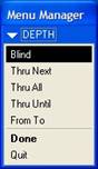
Therefore, go to Insert, Sweep, Protrusion, and the following window comes up.
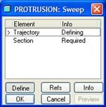
We can see we are currently defining the trajectory. We can also see the following menu manager.

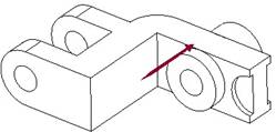
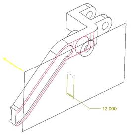
We will pick on the Sketch Traj option to sketch a trajectory. When we do this, pick on the FRONT datum plane for the sketching plane. An arrow appears, indicating the direction of viewing the sketch, as shown in the next figure.
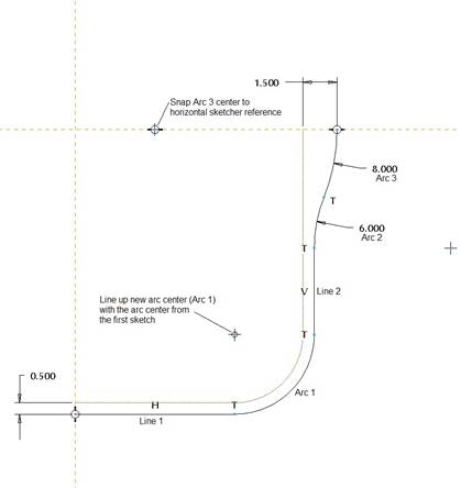
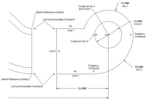
Make sure it is going in the direction shown above, and then click on Okay. In the next menu, pick on the Right option, and then pick on the “I” shaped surface. We are placed into the sketch. For a sketching reference, pick on the top, flat surface of the part as a sketcher reference, and then sketch the following profile.
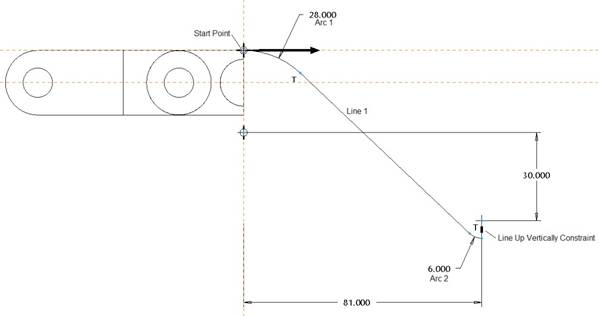
NOTE: Be sure the start point is at the top of the arc where it intersects the solid geometry. The start part can not be out in the middle of the trajectory. The “Line up Vertically Constraint” is applied between the arc 2 center and arc 2 endpoint.
Once your trajectory is done, click on the blue check mark to finish the sketch. You will now have the following menu options.

We can go ahead and use Free Ends, because our trajectory is normal to the surface where the solid geometry exists. If the trajectory were not normal, we might want to use Merge Ends to have the gap filled between the end of the sweep and the existing geometry.
Click on Done to continue. We are now placed into the sketch. Because we already have the profile of the sweep defined (the “I” shape), we can use the Use Edge, Loop option and select the I-shaped surface. Each edge will show the “use edge” constraint symbol, as shown in the next figure.
Click on the blue check mark to complete this, followed by OK in the sweep window. We will see our finished sweep feature, as shown in the next figure.
Save this model at this time before continuing.
Feature 9 – Datum Plane
In preparation for the next feature, we will create another offset datum plane. This one will use the same reference as the last one we created (DTM1), but will be 12mm instead of 10, like we did in the last one. The preview for this datum plane while creating it will look like the following (again, flip the positive side to be visible from the front of the model).
Feature 10 – Extrude
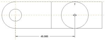
The next extrude feature will actually be disconnected from the model temporarily. If you look at the figure, we can’t see a dimension going from the end of the sweep to the next section. We do see the 140mm distance between the first cylindrical protrusion to the hole on the right side, so we will create the protrusion that generates this hole as the next feature.
For the sketching plane, use the DTM2 plane that we just created, and make sure the viewing direction arrow is facing towards the back of the part. Face the RIGHT datum plane towards the Right. Inside the sketch, we want to use the vertices at the top and bottom end of our swept feature as a reference (as indicated in the next figure). Then, sketch the following profile.
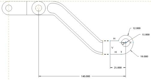
The next figure shows a close-up of the section and what is going on.
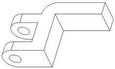
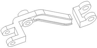
Finish the sketch by clicking on the blue check mark, and then extrude this feature to the front of the part a distance of 38mm. The result is shown in the next figure.
We can see that our protrusion is entirely outside of the rest of the model, but we will be closing that gap in two more features. Save the model.
Feature 11 – Extrude (Cut)
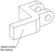
The next extrude feature we are going to create will cut out the opening on the right side of the feature we just created. Therefore, use the bottom, flat surface of the last extrude feature as the sketching plane. Flip the viewing direction arrow so it is facing down, away from the existing extrude feature, and face the flat front surface of the same extrude towards the Bottom.
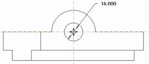
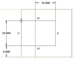
Inside the sketch, be sure to select the silhouette edge of the extrude feature as a sketching reference, as well as the axis that goes through the hole in this feature (you may need to temporarily turn on the axes to select it). Then, sketch the following rectangle and dimension it accordingly.
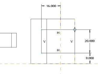
NOTE: The 16 mm dimension is missing from the exercise figure. If you notice, this feature is dimensioned exactly the same as the second feature we created for this model. Therefore, go ahead and add this 16 mm dimension.
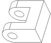
When finished with the sketch, extrude the cut up into the part using the Through All depth option. The finished extrude will look like the following.
Save this model before continuing.
Feature 12 – Extrude
The last extrude for this model will close the gap that exists. We will use the “I” shaped surface as the sketching plane, and face the viewing direction in towards the sweep feature. Face the FRONT datum plane towards the Left.
Inside the sketch, use a Use Edge command, and select the top and bottom edge of the “I” beam profile, but do not select any of the sides. IMPORTANT: Because there are no assumed sketcher references, when you pick on the “Use Edge” command, you will get a warning that no references have been defined, and do you want to continue to sketch. Click on Yes, then proceed to select the top and bottom edge of the “I” shaped surface.
Fill in the sides with two lines to complete the rectangle shown in the next figure (which shows the sketch in a rotated orientation from the 2D sketch view).
Finish the sketch by clicking on the blue check mark, and then use the To Selected depth option to go up to the larger flat surface of the disconnected extrude feature. The finished extrude feature looks like the following.
Notice that we don’t have the semi-circular cut out on this side yet. That will be our last feature for this exercise. Save the model first.
Feature 13 – Revolve (Cut)
We will create a very similar revolved cut to finish this model. For the sketching plane, we are going to pick on the very thin, flat surface shown in the next figure.
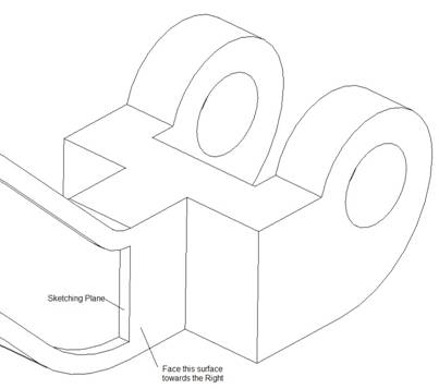
For the reference surface, select the front surface of the sweep, as indicated in the figure above, and face it towards the Right. Be sure your viewing direction is aiming out to the left, away from the end of the sweep.
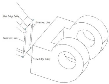
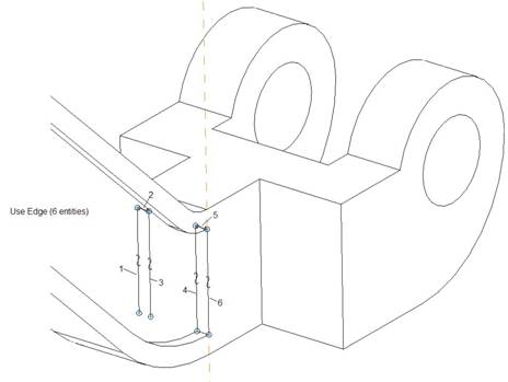
Inside the sketch, we want to use the Use Edge command and select the four vertical edges on the sketching plane, as well as the two short edges at the top of these lines, as shown in the next figure.
Next, sketch a horizontal centerline snapped to the midpoint of one of the vertical lines that we just created, as shown in the next figure.
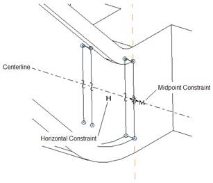
Finally, trim up the vertical lines so only the top half remain, and close off the rectangles with two more short lines. The final sketch looks like the following.

Revolve this cut 360 degrees (which will not interfere with any other geometry in the model), and the final model will look like the following figure.
Save and close this model.
Basket
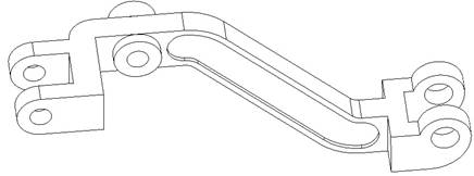
The last exercise in this Lesson, is to create a swept surface for our basket. Open up the Basket part that we created in Lesson 10, which currently looks like the following.
Go to Insert, Sweep, Surface from the menu bar. The Sweep window opens, and we see the familiar menu manager.

This time, we are going to select the Select Traj option (because we have our trajectory already defined by a curve or existing geometry). When we do this, we get the following menu.

Since we have sketched curves in our model, we will use the Curve Chain option (indicated above). Place your mouse over one of the segments of the first sketch in the model (the one with two lines and an arc), and right click until you see the entire curve highlight in blue. Select the curve once it is completely highlighted, and you will get the following menu.

Since we want to use the entire curve as our trajectory, we will select on the Select All option. Had we only wanted to go from one vertex to another on the trajectory, we could have used the From-To option.
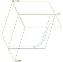
When we click on Select All, an arrow appears on one of the endpoints, as shown in the next figure.
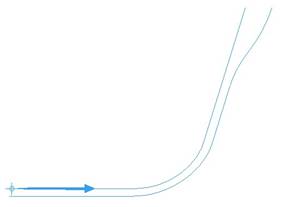
If your start point is not the same as the one shown above, then you will need to click on Start Point, in the menu manager, followed by Next, until you see this vertex highlight, at which point you would select Accept.
Click on Done once your start point is in the correct location, and you will get the following menu manager.
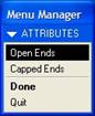
If you are sketching a closed profile (like a rectangle or a circle), you can have the final surface closed off at the ends. We are only going to be sketching a single line, therefore, we will leave the default of Open Ends selected, and click on Done to continue.
We are placed into sketch mode, where we will sketch an angled line dimensioned as shown in the following figure.
When you are done with the sketch, click on OK in the sweep window, and you will have your swept surface as shown in the next figure (in the default orientation).
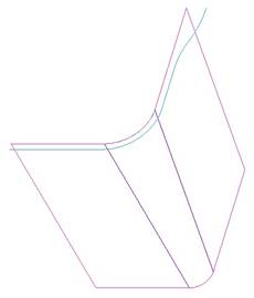
Save and close this model.
LESSON 12 – Blend Feature
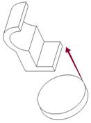
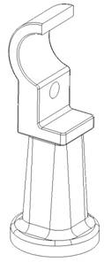
Hand_Rail_Column
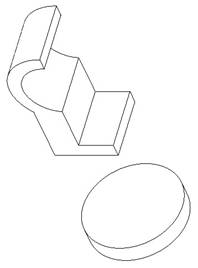
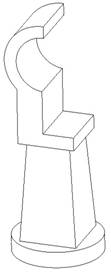
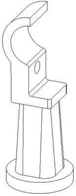
Create a new part called Hand_Rail_Column, and use a metric start part if available. For this model, we will use a combination of datum, extrude, revolve and blend features.
Feature 1 – Extrude
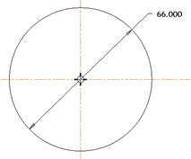
The first feature we will create is an extruded protrusion. The TOP datum plane will be our sketching plane, and we will face the RIGHT datum plane towards the Right. Sketch a single circle as shown in the next figure.
Extrude this circle a depth of 12mm upwards to complete the first extrude feature, as shown in the next figure.
Feature 2 – Extrude
Our next feature is going to be the extruded section at the top of this part. We are going to skip over the blended section for now, and the reason will become apparent as we create the blend feature next.
Therefore, we will create an extrude feature, and use the FRONT datum plane for the sketching plane and face the RIGHT plane towards the Right. We will sketch the following profile.
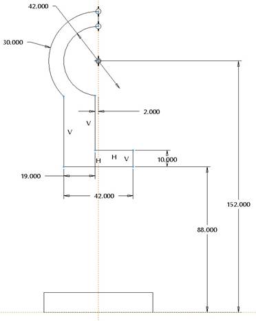
Use a symmetric depth option, and a depth value of 42mm. The finished extrude feature looks like the following figure.
Feature 3 – Blend
The next feature will be our blend that goes between the first and second extrude features. The reason we created the top extrusion before the blend is because of the depth of the blend feature.
Based on the fact that our blend sections are going to be parallel to each other, we will end up using a parallel blend. If you recall from the lesson, if you were to define the depth of the blend sections using a numerical value, that value goes from one section to the next.
Unfortunately, if you look at the design intent of this model, the bottom section of the blend is on the top of the cylindrical protrusion. The depth of the second section (88mm), however, is based off the bottom of the cylinder. Therefore, to preserve design intent, we can’t simply create the blend and use a depth of 76mm (88-12).
We can, however, use references to define the depth instead of an actual value, and that is where the second extrude comes in. By defining the extruded feature’s base at 88mm above the TOP datum plane, we can use that base as the stopping point for our blend.
Therefore, go to Insert, Blend, Protrusion, and you will get the following menu.
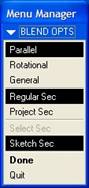
We will keep all of these default options to create a parallel blend where we use regular sections that we sketch. Click on Done, and this brings up the blend window, as shown in the next figure.
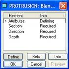
We are currently defining the attributes, and our choices are shown in the following menu.

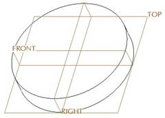
Since we only will have two sections, either one of these choices will do the same thing. Therefore, we will keep the default of Straight, and click on Done to continue. We are asked to pick on a sketching plane, so we will pick on the top circular surface of the first extruded cylinder. When we do this, an arrow appears indicating the direction of feature creation, as shown in the next figure.
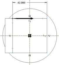
If the arrow is going in this direction, click on Okay. If not, flip it and then hit Okay. Next, select Bottom, and pick the FRONT datum plane. When we are placed into sketch mode, we will start by sketching two centerlines on the existing sketching references, followed by a square with a side of 42mm, as shown in the next figure.
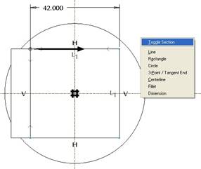
Once you have the first square sketched, right click out in the working window, and select Toggle Section, as shown in the next figure.
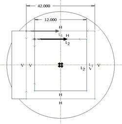
This should mute your first square, and now you will sketch a second square with a side length of 32mm, as shown in the next figure. NOTE: You do not need a second set of centerlines, the first ones should still work for your symmetry constraints.
Once you have this second circle sketched, click on the blue check mark to complete the sketch. You will get the following menu to select the depth options.
We will select the Thru Until option, followed by Done, and then select the square surface at the bottom of the second extrude feature. Once you select this, click on OK to complete the feature, which is shown in the next figure.
Feature 4 – Extrude (Cut)
The next feature will create the hole in the side of the second extrude feature. Therefore, for our sketching plane, use the RIGHT datum plane. Make sure your viewing direction is going back into the model. Face the TOP datum plane towards the Top. Inside the sketch, select the bottom surface of the second extruded feature to use as a sketching reference, and sketch the following circle.
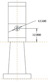
Extrude this cut back into the part using the Through All option, and your feature looks like the following.
Feature 5 – Revolve (Cut)
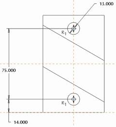
The last feature we will create will be a revolved cut. We will use the FRONT datum plane as the sketching plane, and face the RIGHT plane towards the Right. Sketch a vertical centerline on the RIGHT sketcher reference, and then sketch the following.
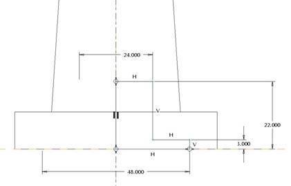
NOTE: This sketch consists of six lines forming an “L” shape. Use symmetrical dimensions to represent the diameters of the holes.
The final model, shown in hidden line mode, looks like the following figure.
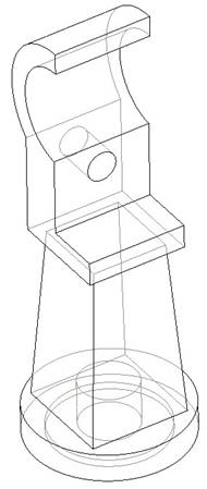
Save and close this model for the next lesson.
LESSON 13 – Rounds
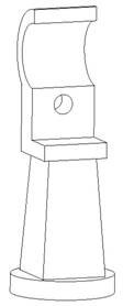
Hand_Rail_Column
Open up the Hand_Rail_Column that we created in the last lesson. We are going to add rounds to this model. The goal when creating overall part rounds is to try to create them in the following order:
1. Individual edges/chains that create tangencies on other edges that must be rounded.
2. Edges that share the same radius value that do not intersect.
3. Edges that have different round values that do not intersect can be done in the same round as #2 as another set.
4. All other rounds.
Therefore, keeping this in mind, we may want to create our first round feature using the following:
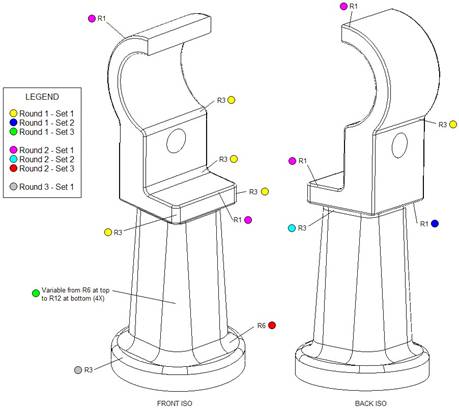
NOTE: I would recommend viewing this figure in color – either printed that way or electronically.
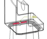
Round 1 – Set 1
Create a new round feature. Change the radius value to 3, and select all of the edges shown in the colored schematic above using the Ctrl key so they are all part of a single round set. The preview for this first set will look like the following.
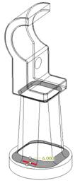
Round 1 – Set 2
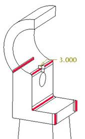
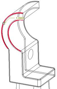
Now, without holding down the Ctrl key, select the edge indicated by the color schematic for Round 1 – set 2. Change the diameter once selected to 1.0. The preview for this looks like the following. NOTE: You are still in the same round feature, so do not complete the round yet. The first round set should be muted.
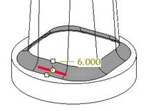
Round 1 – Set 3
Once more, without using the Ctrl key, click on one of the slanted edges on the blend feature. When the radius appears, right click on one of the drag handles, and select Add Raidus to turn this round into a variable round. When the two dimensions appear for this selected line, change the one near the base to 12.0, and the one near the top to 6.0. Now, hold down the Ctrl key, and select the other three slanted lines and add them to the same round set. The preview for this set will now look like the following.
Click on the green check mark to complete this first round feature, and you will see the following.
Round 2 – Set 1
Start a new round feature. Change the radius to 1.0 and select on one of the edges indicated in the color schematic as the Round 2 – Set 1. Because we rounded all of the edges in the first round, a tangent chain should exist that propagates this new round all the way around the head. Continue using the Ctrl key to select the other edge, as shown in the following preview.
Round 2 – Set 2
Release the Ctrl key, and select one of the edges at the intersection of the blend feature and the extrude feature at the top. Again, a tangency condition should propagate this round along the entire intersection. Change the radius to 3.0, and the preview will look like the following.
Round 2 – Set 3
Again, without holding down the Ctrl key, select one of the edges at the bottom of the blend feature where it meets the cylindrical extrusion. Change the radius to 6.0, and the preview should look like the following.
The preview for this entire round feature should look like the following at this time.
Click on the green check mark to complete our second round feature, and the model will look like the following.
Round 3 – Set 1
For our last round feature, there will only be one round set. Create a new round, and change the radius to 3.0. Select the circular edge at the top of the first extruded cylinder. The preview for this round will look like the following.
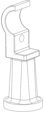
Click on the green check mark to complete this round, and our model is now finished. The following figure shows the completed model with the three round features.
Save and close this model.
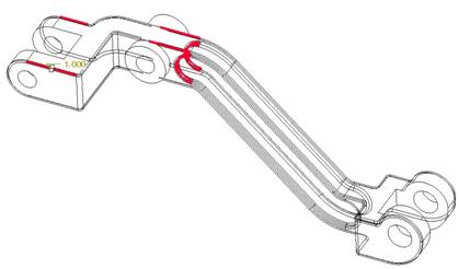
Dash_Pot_Lifter
Using the same method as in the last model, we will create the rounds for the dash pot lifter using the following round features and round sets. NOTE: Again, this schematic is better viewed in color for clarity.
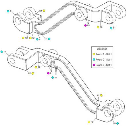
Round 1 – Set 1
Create a new round and set the radius value to 2.0. Select all of the edges using the Ctrl key indicated in the color schematic. The preview for this round set will look like the following.
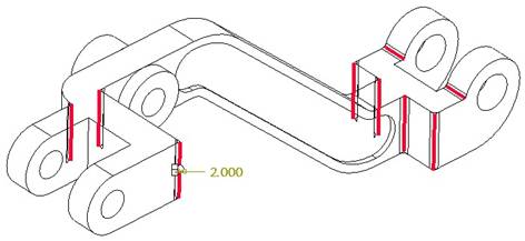
There are no other sets for this round feature. The finished feature looks like the following.
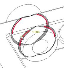
Round 2 – Set 1
The next round will take advantage of tangency conditions that now exist. Therefore, create a new round feature, change the radius to 1.0, and then select on the appropriate edges indicated in the color schematic. The preview for this round set will look like the following.
Again, there are no other round sets for this round feature. The completed round will look like the following.

Round 3 – Set 1
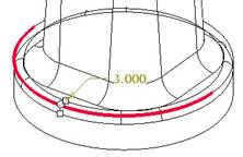
The last round has to be done separately, and after the second round feature. These are the rounds that go around the cylindrical protrusion. Even though they share the same radius value as round 2, the way that the cylinder intersects the existing geometry, creates a weird transition that even the Transition tool in the round feature can’t address.
Therefore, we will create our third round feature, and select the remaining edges to round. The preview for this round set looks like the following figure.
NOTE: You have to select all four circular edges, because no tangency condition exists at the top or bottom. The final model with this round feature completed looks like the following.
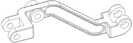
Save and close this model.
LESSON 14 – Chamfers
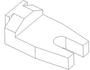
Create a new part called Finger_Guide. We are going to use a combination of extrude and chamfer features to complete this model.
Feature 1 – Extrude
The first feature will capture most of the shape of the model as seen from the top view (with the exception of the chamfered edges. Therefore, we will use the TOP datum plane as the sketching plane, and face the RIGHT plane towards the Right.
Sketch the following profile. NOTE: Take advantage of symmetry to reduce the number of required dimensions.
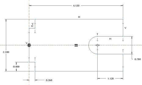
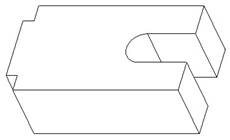
Extrude this profile 1.5 inches to create our first extrude feature, as shown in the next figure.
Feature 2 – Extrude (Cut)
The second feature will be a cut that leaves the “L” shape seen in the Front view of the exercise. Therefore, use the FRONT datum plane as a sketching plane, and face the RIGHT datum plane towards the right.
Inside the sketch, select the top and right surface of our first feature as sketching references, and then sketch and dimension the following rectangle.
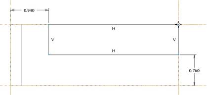
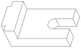
Extrude this Through All on both sides of the datum plane using the Options slide-up panel to define the depth in both directions. The final result is shown in the next figure.
Feature 3 – Chamfer
For this chamfer feature, we are going to create three different sets. One of the sets will even have transitions to deal with.
Set 1
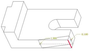
For the first set, we will start by clicking on the chamfer icon, and then select the following edge.

By default, the scheme is D x D, and in our example, the “D” value is 0.060. We will change the scheme to D1 x D2, and then enter 1.9 and 0.3 for the dimensions, as shown in the next figure of the preview for this scheme.
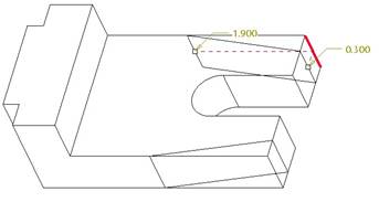
Set 2
For the second chamfer set, we will pick (without using the Ctrl key) the equivalent vertical edge on the back side of this model. You may need to use the “Flip” button to the right of the D2 field to get the right scheme, as shown in the next figure.
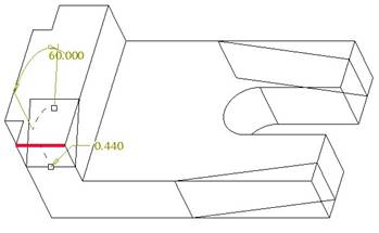
Set 3
For this set, we will start by picking on the horizontal line that forms the top of the “L” front surface. Do not use the Ctrl key, so you can create a third set. Change the scheme to Ang X D, and use 60.0 for the angle and 0.44 for the “D” value. Flip the dimensions if necessary to get the following.
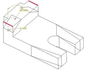
Now, hold down the Ctrl key and select the equivalent edge on the back side. The preview should now look like the following.
If we were to click on the preview button (the one with the glasses in our dashboard), we would see the following.
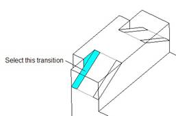
Clearly, the third chamfer set is not ending properly – it should go all the way to the back of the model. Therefore, we will need to use transitions to fix this. Click on the transitions button in the lower left corner of our dashboard. Next, pick on the following transition (shaded in blue in the next figure for more clarification).
When we select this, we can see that the transition assigned right now is called Default (Stop Case 2). We will change this to Stop Case 1, which looks like the following.
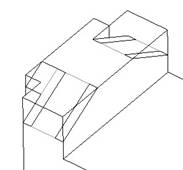
If we click on the preview button now, we see the following.
This looks correct. Now, click on the equivalent transition on the other side. Its default transition is Default (Stop Case 1). We will use the Stop Case 2 for this one, and now our transitions are correct on both sides.
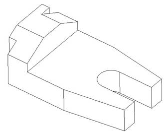
Finish out of this chamfer feature, and our model is done, as shown in the next figure.
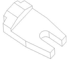
Save and close this model.