Lesson 160

Lesson Objective: In this lesson, we will learn about Cam Followers.
USAGE OF CAM-FOLLOWERS
A Cam-Follower is used to simulate an object moving along the surface of another object, or when the motion of an object must be stopped at the surface boundary of another object. A cam-follower can be used when other mechanism connection types fail to capture the way in which the objects touch each other.
For example, a planar connection always assumes two planar surfaces will remain co-planar. This will not allow the components to separate from each other, or allow one surface to rotate away from the other while still touching.
You will still need to create other mechanism connections, such as a Planar connection to control the motion of the component that is free to move, and to create any servo motors.
EXAMPLE 1 – SIMPLIFIED CAMSHAFT
To demonstrate a traditional cam-follower application, we will look at a simplified version of a camshaft that you would find in an automotive engine. Therefore, open up the Camshaft.asm assembly. It will look like the following.
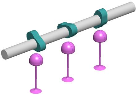
This assembly consists of four components. There is one shaft that contains three green extruded features. These three green extruded features will (as the shaft turns around) contact the magenta levers, causing them to rock up and down.
Go to Applications, Mechanism, and you will see that we already set up some initial connections and servo motors, as shown in the next figure.
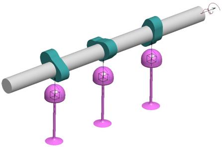
The main shaft has a pin connection, and a servo motor on this pin connection. The servo motor will rotate the shaft 1440 degrees (4 complete rotations) in 10 seconds. Each magenta lever has a slider connection allowing it to move up and down.
We will now need to add three cam-followers to get the magenta levers to touch the three green extrusions.
Cam-Follower 1
To create a cam-follower, you click on the following icon in the Mechanism toolbar.
![]()
This brings up a similar window to what we have seen before.
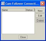
Click on New and when the next window appears, give this a name of Lever1_Cam. The window will look like the following:
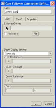
When you define a cam, you must pick surfaces or curves/edges on two different components. In this window, there are three tabs – Cam1, Cam2 and Properties. Cam1 is used to pick all of the surfaces for the first component. Cam2 is used to pick all of the surfaces for the second component, and the Properties tab is used to define additional properties of the entire cam.
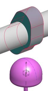
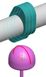
It does not matter which component is cam1 or cam2, therefore, we will pick all of the surfaces that go around the green protrusion closest to the servo motor end. You could hold down the Ctrl key and select each surface, or you can click in the checkbox called Autoselect, and then pick one of the tangent surfaces. All other tangent surfaces to that surface should get selected, as shown below.
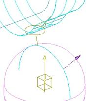
Once all of the surfaces have been selected, click on the middle mouse button to accept them. A light blue outline of the cam 1 geometry will be shown on the model, as we can see in the next figure.
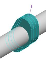
A purple arrow points towards the outside surface of the cam geometry. You can flip it if it is not going in the right direction.
Once you have this outline, the window looks like the following.
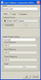
We can see the surfaces on the CAM_SHAFT component listed, but the depth display setting is currently set to Automatic. Whenever you have a completely closed boundary of tangent surfaces, like we do in this case, it is always better to let the depth of the cam be generated automatically. We will see how to set other depth options in the next tab.
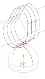
Pick on the Cam2 tab. We will now select the two curve segments that form a half-circle on the top of the magenta cam that sits underneath the first set of surfaces that we used for Cam1. Both curve segments should highlight in a bold red when selected, as shown in the next figure.
Once we have both curve segments selected, click with the middle mouse button to create the second cam. A cam symbol appears between the two components, as we can see in the following figure.
When we click on OK, the two components will snap together, as shown in the next figure.
Cam-Follower 2 & 3
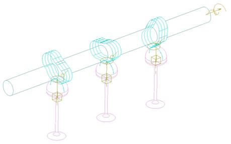
Repeat this same process to create the second and third cam-followers (called Lever2_Cam and Lever3_Cam). When done, our model will look like the following.
We will now click on the analysis icon, select the Cam_Motion analysis that was already created, and then hit the “Run” button. You should see the rod rotate that contains the three cams. As each cam goes around, the magenta part beneath it will move up and down to maintain contact with the cam at all times.
Watch your playback and save your results.
EXAMPLE 2 – LIFTOFF (KEY AND LOCK)
In our first example, we forced the two cams to always touch each other. This is not always realistic, or even possible. In cases where the cams must stop when they encounter each other, but not have to always touch, we will enable liftoff for our cams.
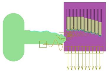
To demonstrate this, we will open up a model called Lock_Cam.asm, which initially looks like the following.
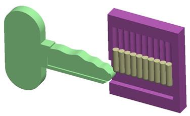
In this model, the green key will slide into the lock (half-model) and then exit again. As the key moves into the lock, the 10 individual little gold bits should slide up their respective tracks just enough to stay in contact with the key surface as it moves under them.
Therefore, we need to set up cams for each of the bits so that when the green key comes into contact with it, the bit will move up. But, as you can easily see, we can not force them to touch at all times, because the farthest bit from the key won’t come in contact with the key until it is all the way in the lock.
To start, go to Applications, Mechanism. We should see that we already have some slider connections set up, as well as a servo motor. The servo motor is using a table-driven profile to move the key in and out in 6 seconds. An analysis is also set up to save some time. Now it is time to create the cam followers.
Cam Follower 1
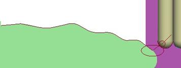
We will start by clicking on the cam tool in the feature toolbar, and then click on New to create our first cam. Accept the default name to save some time. For Cam1, we will select the wavy surface of the key and the smaller rectangular one to its right, as shown in the next figure.
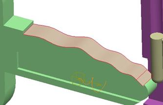
Note: Using AutoSelect will not work in this case, as the surface is not a completely closed, tangent chain of surfaces. Once selected, click on the middle mouse button, and you will see the surface mesh in blue with a purple arrow pointing up from it.
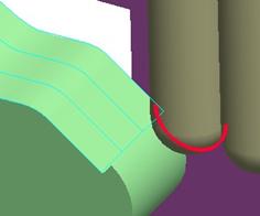
Now, click on the Cam2 tab, and select the half-circle curve at the bottom of the first bit, as shown in the next figure.
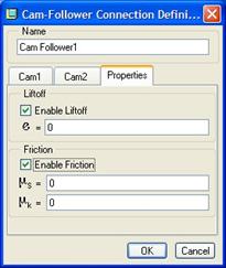
Click on the middle mouse button to complete this second cam reference. Now, click on the Properties tab. At the top, there is a check box to enable liftoff. Click in this box, and the window will look like the following.
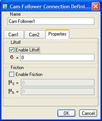
We will not enter a coefficient of restitution at this time, so leave it at zero. Click on OK to complete our first cam follower. What you will notice this time is that it does not automatically snap the two cam parts together, like it did in the camshaft. This is due to the liftoff, and we can see our final cam in the next figure.
Cam Followers 2-10
Repeat this same process for the remainder of the cams that we need to define. For each cam, use the same surfaces on the key, and the corresponding half-circle curve on the bit. Our final cam definition for this assembly is shown in the next figure (from a FRONT, No Hidden view).
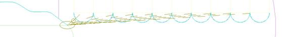
There are actually 10 cam symbols, but they are on top of each other. You should be able to see the 10 individual dashed lines going to the individual bits. Now, click on the analysis tool, and edit the existing Key_Insertion analysis. It will look like the following figure.
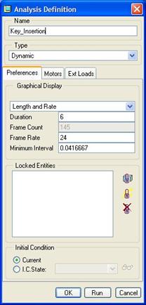
You might notice that I’m using a Dynamic analysis instead of a Kinematic, as we have all along. This is not necessary for cams, but will be in a later lesson. Turn on shading of your model, and click on Run to watch what happens.
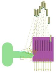
What do you notice? Pretty weird, isn’t it? It actually makes sense if you understand what is going on. First of all, the cams are doing what they are supposed to do – as the key comes in contact, the bit gets pushed upwards. Unfortunately, because we are running a dynamic analysis, impact forces are causing the bits to react to this upwards motion. This wouldn’t necessarily be a problem except that we have nothing to bring the bit back to the key. The key continues upwards until it runs out of energy, and then hangs, as shown in the next figure.
Now, if we had enabled gravity (which we will learn in a later lesson), the bits would have come back down, but would have passed through the bottom of the lock never to be seen again. If the key were in the way, the bits would come back down, bounce off the key, to the best of their ability – based on the coefficient of restitution, and continue this process until all of the dynamic energy was spent.
Suffice it to say, that we are not done with our model, but we will have to wait until a future lesson. For now, change the analysis type to Kinematic, and then use Mechanism, Connect to bring the parts back to their starting position. Re-run the analysis, and what do you see?
This time, the bits were pushed up, out of the way of the key as it moves, and then stopped at their highest location. The Kinematic analysis does not force a collision reaction with the bits and the key, and gravity (or lack thereof) is not even factored in – the bits simply move using the cams. We will start to see dynamic analyses a little more in the upcoming lessons. For now, set the analysis type back to Dynamic, and then save and close this assembly for later.
FRICTION
In addition to coefficient of restitution, we have the ability to specify any frictional coefficients that may exist based on the two cam materials. You would specify the coefficient of friction based on the two materials that are in contact. For example, if one part is brass and one is steel, you would have one coefficient. If another part were plastic and it hit the same steel part later on, you would define a second cam with a different coefficient of friction.
Any dynamic analysis performed on this cam would take these coefficients into account to give the most realistic animation possible.
We could have actually used this for our rolling tire down the slide (in Lesson 15), instead of defining a rotational servo to simulate the tire rolling. Friction is accessed on the Properties tab in the cam definition, as shown in the next figure.
You can define a static (s) coefficient, as well as a dynamic (k) coefficient. The static coefficient must be larger than the dynamic – which is based off of valid empirical data.
CAM DEPTH
In mechanism, you are only allowed to pick on flat or cylindrical-like surfaces for cams. Spherical or surfaces that bend in two or more directions are not permitted.
Similarly, you can pick straight curves, or rounded curves, as long as they line in a single plane.
When you select a flat surface or a straight edge/curve for the cam, the system does not automatically calculate the depth of the cam. Therefore, you must select a point/vertex that represents the front of the cam surface/curve, and one that represents the back of the surface/curve. You can also specify a depth other than the distance between the two points.
LESSON SUMMARY
Cams are used when two components must collide or remain touching each other during the motion. You must be careful picking references for cams, as they are a bit touchy. In addition to specifying liftoff, you can also enable friction and coefficient of restitution for the collision of the bodies.
EXERCISE
Open up the Maze.asm file. It should look like the following.
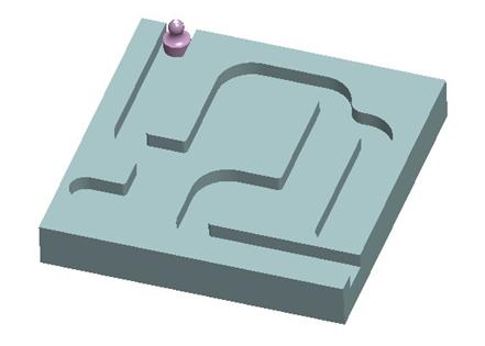
The obvious objective for this exercise is to capture a realistic set of constraints that will allow you to move your game piece around the maze without cutting through any internal walls. Test your cam(s) with the drag functionality. We will not be creating an analysis for this assembly.
Save and close the assembly when done.