|

Lesson Objective: In this lesson, we will learn about the Slot-Follower.

USAGE OF SLOT-FOLLOWERS
There are many times when you need to move a component along a path that does not fall into a straight line, or a revolved trajectory. Using traditional mechanism connections learned so far, we are unable to accomplish this.
To be able to do this, we will need a Slot-Follower. A slot-follower works by aligning a datum point to a datum curve. The point rides along the curve. You can define the ends of the curve to limit the travel of the point.
A slot-follower is generally used in conjunction with other mechanism connections, as the slot-follower itself can not have servo motors attached to it.
You would use a slot-follower to simulate such conditions as:
· A roll-top desk
· A car moving along a non-straight path
· The center rails of an accordion-type mount (such as the one we saw with the mirror assembly)
· Capturing a three-dimensional path for the end of a robot
· Any component that must move along a non-straight path
EXAMPLE 1 – BEVEL GAUGE
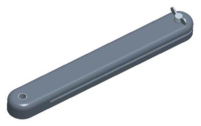
This is a simple example that shows how you might use a slot-follower in parallel with a planar connection. To demonstrate this, open up the assembly entitled Bevel_Gauge.asm, which should initially look like the following.
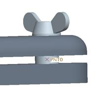
We are going to turn on the view of datum points to reveal a datum point that lies in the middle of the screw where the blade will go, as shown in the next figure.
Little red flags may be going up in your mind right now. If the datum point is supposed to follow a curve, then shouldn’t the curve reside on the stationary part of the assembly? That assumption might seem logical, but it does not matter for this tool.
The curve can (in effect) ride along the point. Therefore, it does not matter which component has the point and which one has the curve.
Now, we are going to assemble in the BG_Blade.prt component. When we are in the placement window, we will go to Connect to activate mechanism connections, and then select Planar from the connection type.
We will select the two planar surfaces shown below.
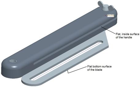
Once both are selected, click on OK to complete the placement. Then, go to Applications, Mechanism. We can see the planar connection symbol on our assembly, as shown in the following figure.
If you recall from the lesson on planar connections, this blade is now free to rotate about an axis normal to its large flat surface, and it is also free to move within the plane that goes through its large flat surface.
We will need to limit its motion so that the slot in the center of the blade rides along the shaft of the wing screw (where the datum point is). You will notice that the blade part has a datum curve through the slot.
Slot-Follower Definition
To create a slot-follower, we will click on the following icon in our feature toolbar.
![]()
When we do, we get the following window.
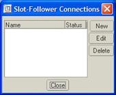
This looks like the same window we saw for creating servo motors or analyses. We will create a New slot-follower, and call it Gauge_Slot, as shown in the new window that appears.
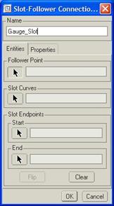
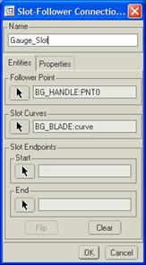
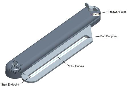
We are now prompted to select the Follower Point. Pick on the datum point. Then, we are asked to select the Slot Curves. If you need to pick more than one curve, you can use the Ctrl key, or the Shift key to get curve chains. We will pick on the datum curve in the middle of the slot.
At this time, the window should now look like the following.
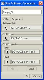
Defining the end points is optional, so we are not automatically prompted to select them. Therefore, we will click on the button with the arrow for the Start point, and select the end of the datum curve closest to the rounded edge of the blade.
Next, we should be prompted for the End point, so we will pick the other end of the curve (closest to the sharp edge of the blade). There really is no apparent reason for the order in which you pick the points. The window should look like the following figure.
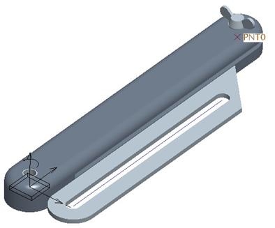
Our selection of the objects corresponds to the following figure.
Click on OK to complete the slot-follower, and we should see the following.
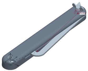
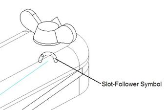
The blade snapped over to the handle at the closest endpoint selected. Click on Close to complete the defining of slot-followers. The symbol for the slot-follower can be seen in the figure below.
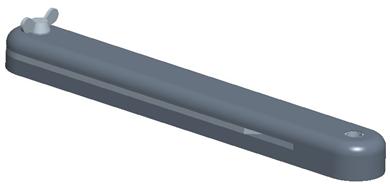
Now, click on the drag tool, and pick anywhere on the blade part. Notice that as you drag it around, it is limited in its motion. You should be able to simulate opening and closing the blade. The following shows an example of the blade completely closed.
Save and close this assembly.
ANIMATING SLOT-FOLLOWERS
In the example of the Bevel_Gauge, would we be able to create a servo motor? Technically, we had the planar connection which had three different components (two translations, and one rotation), so we could have created a servo motor that might have been able to animate the blade.
To see a demonstration, look at the BEVEL_GAUGE.mpg movie in your training directory. This movie was done by creating two servo motors, one for the rotational component of the planar connection, and the other for the translational component that extends from the side of the handle.
On your own, try to duplicate this animation with your bevel gauge assembly.
EXAMPLE 2 – WHEEL ROLLING DOWN SLIDE
Here’s a great example of how you can animate a slot-follower connection. We will simulate a car tire rolling down a slide. We want to simulate not only the wheel following the contour of the slide, but we also want to have the wheel turning.
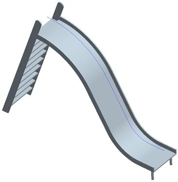
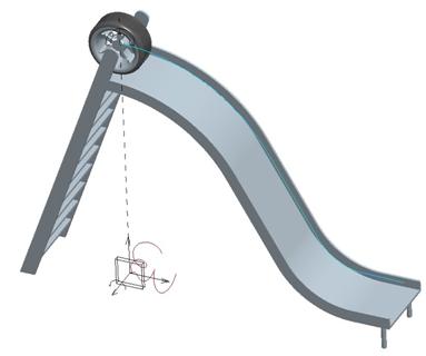
Therefore, open up the assembly entitled Rolling_Wheel.asm. It will contain the slide component, as shown in the next figure.
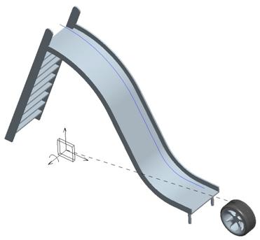
Turn on the display of datum planes and assemble in the Wheel.prt component. Use a Planar connection and select the FRONT datum planes on both models. The wheel will snap to the center plane of the slide.
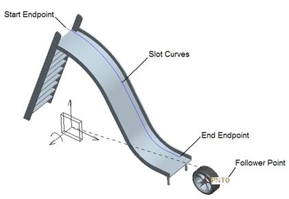
Next, we will go to the slot-follower tool ( ![]() ) and create a new
slot-follower called Wheel_Slot. When prompted for the different
entities, pick the ones shown in the figure below.
) and create a new
slot-follower called Wheel_Slot. When prompted for the different
entities, pick the ones shown in the figure below.
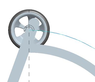
Once the slot-follower is created, use the drag tool and move the wheel to the top of the slide at the end of the curve. Do not worry if the tire rotates as you move it up, because we will adjust the settings for the planar connection.
Joint Settings – Planar Connection
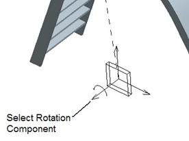
We will start by clicking on the rotational component of the planar connection symbol, as shown in the next figure.
Right click and go to Joint Settings. We should see its current rotation value in the field. Type in 0 and then go to the Regen Value tab to set the model to regenerate using the “0” value. From a FRONT view, our wheel should look like the following.
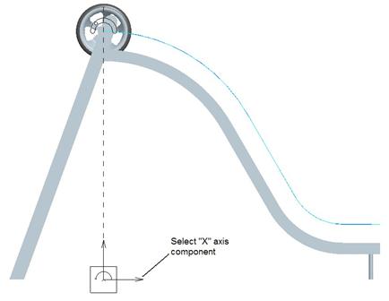
Next, we will click on the “X” axis component of our planar connection, as shown in the next figure.
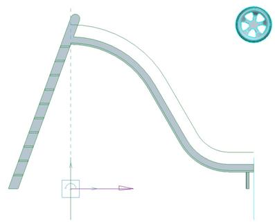
Go to the Joint Settings for this component and type in 0 in this field. It should keep it at the very left side of the curve. Go to Regen Value and make sure the box is checked to always regenerate at “0”. Then, go back to the field and type in 120. The wheel should move all the way to the end of the slide (even though it won’t graphically follow the curve at this time), as we can see in the following figure.
Click on OK to complete these settings. The wheel should be back at the left end of the curve. Now we can set up servo motors to control the motion.
Rotational Servo Motor
The first servo motor will be used to rotate the tire. We will create a new servo motor called Tire_Rotate. Be sure to pick on the rotational component of the planar connection symbol, and then click on the Flip button to rotate the tire clockwise.
We will use a Ramp value to control the rotation, but we need to figure out what our B value will be.
To do this, we will have to do some calculating. The outside diameter of the tire is 24 inches. Therefore, the perimeter of the wheel is pi*24 ~ 75.3982 inches. The total distance that the tire will travel (based on a curve sitting right on the slide where the wheel touches it) is 158.177 inches.
Therefore, the total number of rotations the tire will make in that distance is:
# Rotations = Distance / Perimeter = 158.177 / 75.3982 = 2.098 rotations
Since we have to enter the value in terms of degrees over a time frame (assuming a 10 second animation), we will have our value of B.
B = (# Rotations)*(360 Degrees/Rotation)/10 Seconds = 2.098*360/10 = 75.528
In other words, the tire will rotate 755.28 degrees over the 10 second animation. Therefore, enter A=0 and B=75.528 in the fields provided. Check the graph to make sure it is correct. Click on OK to complete this first servo motor.
“X” Vector Servo Motor
We will create a second servo motor called X_Motion, and pick on the “X” vector of the planar connection symbol as we had done before.
This one is a little trickier, but we already saw the answer in the joint settings. We know the total horizontal travel from the start point to the end point is 120 inches. To be safe, we will assume 119.5 inches (to give us some room for error). We don’t actually need to know the curve length that the slot-follower uses. We could have just as easily used the “Y” vector data instead, but we already set the “X” vector.
Therefore, we want to travel 119.5 inches in 10 seconds. So we will use a Ramp setting for this motor, and set A=0 b=11.95. Check the graph to make sure it is set properly, and then click on OK to complete this motor.
We should see two servo motors on our Planar joint connection, as shown in the following figure.
Analysis
We are now going to set up our analysis. First, run Mechanism, Connect to put our wheel back at its starting position.
Create a new analysis called Rolling_Tire, and keep the timing options at their defaults. On the Motors tab, make sure both servo motors are present and going from Start to End for both of them.
Run this analysis, and you should see the tire rotate while it travels down the slide. When you are done, capture an MPEG movie. To see a completed movie, look at the Tire_Roll.mpg movie file in your training directory.
Save and close this assembly.
LESSON SUMMARY
A Slot-Follower is used to capture a path an object travels that lies outside of a straight line (as you would get with a slider), or even a plane (as you would have with a planar connections).
You specify the point, curve and endpoints of the curve (if desired). To create animations, you must have at least one other mechanism connection to control.
EXERCISE
Open up the assembly called SLEX.asm (SLot EXercise). It contains a base with a track cut out in it, as shown in the next figure.
The goal for this exercise is to assemble in the SLEX_Ball.prt component, and have it follow the track. We want to have the ball start from the long straight section (on the left) and end back at the front on the smaller straight section (on the right).
Try to create an animation that will smoothly move the ball around the track. When I say smoothly, I mean to try to keep the ball at a reasonably consistent velocity when moving around the track.
HINT: You will need to break up the servo motors at locations that are not a sharp transition for either the X or Y axes of the planar connector.
To see an already created movie, open the SLEX.mpg movie file in your training directory.