Lesson 140

Lesson Objective: In this lesson, we will learn about the rigid and weld connections, which are very similar to each other, but have special circumstances when you would use one over the other.

DIFFERENCE BETWEEN RIGID AND WELD CONNECTIONS
Rigid and Weld connections are both used when you want to connect two components so they do not move relative to one another. There are no open translational or rotational degrees of freedom.
Weld connections take two coordinate systems and completely align them (x axis on x, y axis on y, and z axis on z). There is only the single joint that exists.
A Rigid connection allows you to use typical assembly constraints (such as align, mate, insert, etc.) and group them into a single mechanism connection constraint. Rigid constraints can still leave a component “packaged”, while a weld constraint completely fixes the component.
Okay, so that’s nice, but what does it really mean? The biggest difference is how it treats sub-assemblies that also contain mechanism connections. Up to this point, we have only worked in top-level assemblies. We will now get into a sub-assembly condition, and really see the difference between the two connection types.
EXAMPLE – Robot Assembly
We will look at a robot assembly that is very similar to the one we saw in the lesson on planar constraints. Therefore, open the RW_0.asm assembly. It will look like the figure below.
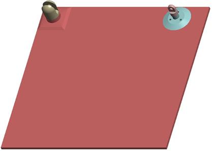
We have intentionally modified the wheel part in this assembly so the cylindrical assembly that connects the left and right sides will not have to rotate downwards as it did in the planar robot example.
Now, open up the RW_3.asm assembly. It will look like the following.
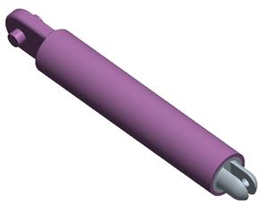
In this assembly, the gray part (RW_3b) is initially completely seated into the purple part (RW_3a). There is a slider connection used on the RW_3b part so that it can slide in and out of the RW_3a part.
Close this assembly, and go back to the RW_0 assembly. Assemble in the RW_3 assembly but leave don’t select any placement constraints yet.
Mechanism Constraints - Pin
Technically, we could assemble this assembly in using two pin connections (one for the end of the RW_3a component, and one for the RW_3b component. This would be acceptable, and would allow for a full range of motion.
We, however, are not going to do this, and to avoid having to do this, I modified the wheel part to make it higher so the axis of the RW_3 assembly will be completely horizontal when assembled.
Rigid Connection
We will start this demonstration by using rigid connections. Therefore, click on Connect to activate mechanism constraint mode, and then change the connection type to Rigid. The window will look like the next figure.
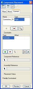
When you select on Rigid, you see the traditional placement constraint window in the middle. We will now select on the model to add inserts, aligns, mates, etc.
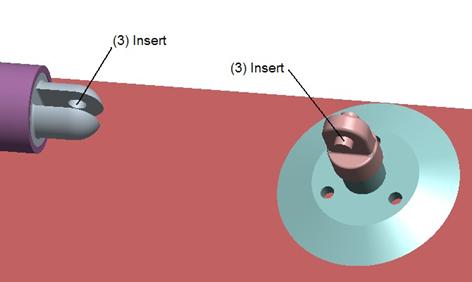
Therefore, start by picking on the following references to create an insert and a mate respectively (for the mate use an offset of 0.0).
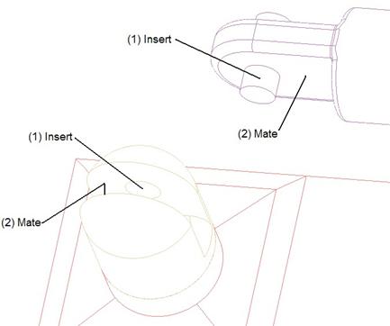
Once we select these two sets, the cylinder assembly will snap into place, and we will still have one additional constraint to add. We will choose an Insert constraint, and select the following two references.
We might be expecting to see the RW_3b component slide out to complete the constraint, but it does not. Instead, we get a warning in our window that the placement constraints are invalid, as shown below.
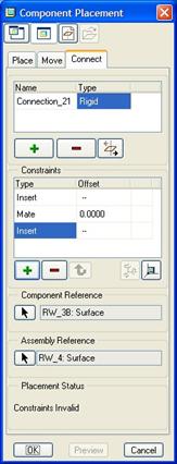
This is one of the main distinguishing factors of a Rigid connection. It temporarily disables any mechanism connections within the sub-assembly being assembled. Therefore, it treats the entire RW_3 assembly as a single blob, and that blob is not long enough to validate the last insert.
Click on Cancel to return to the assembly.
Weld Connection
We will go ahead and click on the assemble component again, and pick on the same RW_3 assembly. When it comes in, click on the Connections tool, and change the placement type to Weld. The window will look like the following.
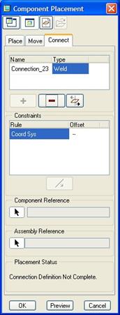
We are required to select two coordinate systems to align. We will pick the ones labeled (1) in the following figure.
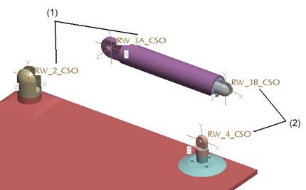
The assembly will snap to reflect this, as shown in the next figure.
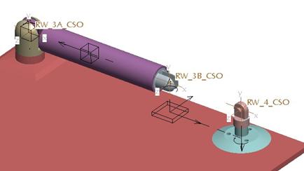
Now, click on the green “+” button to add a new weld connection, and pick on the two coordinate systems labeled (2) in the previous figure. In this case, the end of RW_3b will slide out to connect up to the top of the wheel, as shown in the next figure.
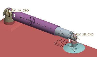
The other thing you might have noticed is that there is an actual joint symbol for the Weld, where there wasn’t one for the Rigid connection. This means that not only will it update the sub-assembly mechanism connections, but you can also calculate reaction forces at the weld points.
The key is to use a coordinate system on the components that you want to weld together.
If you want to test this to make sure it worked, go to Applications, Mechanism, and run the Testrun1 analysis. It should go through the correct motion.
WHEN TO USE WHICH ONE
The general rules of thumb are as follows:
· If you are assembling in a single component that does not move relative to any component in the top-level assembly, then any method will work. I recommend using the Rigid connection for consistency.
· If you are assembling in a single component that must move, then use one of the traditional mechanism connections (pin, slider, etc.).
· If you are assembling in a sub-assembly that does not have any mechanism connections within it, then a Rigid connection or a Weld connection will both work, but the Weld connection will allow you to also calculate reaction forces. A Rigid connection will not.
· If you are assembling in a sub-assembly that has mechanism connections within it, and where it connects at the top level must be able to move, then you should use traditional mechanism connections (pin, slider, etc.).
· If you are assembling in a sub-assembly that has mechanism connections within it, and where it connects does not have any motion, then you should use a Weld connection.
LESSON SUMMARY
Rigid and Weld connections both assume that no motion is necessary at the location in which the component is assembled. For sub-assembly usage, the choice of using Rigid versus Weld will depend on whether there are internal mechanism connections.
Any time a component (whether it is a sub-assembly or a single part) is assembled at locations where motion will occur, you should use traditional mechanism connections, such as pin, slider, planar, etc.
To use the Weld connection, you must have a coordinate system for the component and the assembly. These coordinate systems will be aligned.
EXERCISE
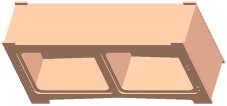
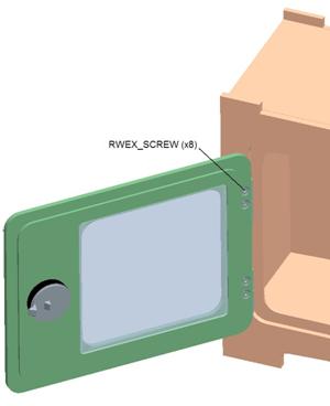
Open up the assembly entitled RWEX.asm. It currently contains a sub-assembly that represents a completely welded frame, called RWEX_CABINET, as shown in the next figure.
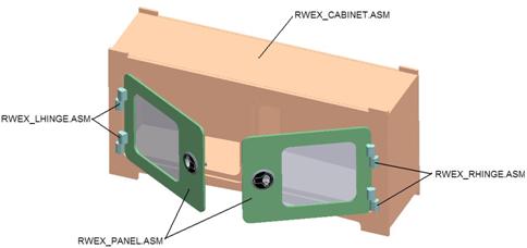
We are going to assemble some additional sub-assemblies and some individual screw components until we get the following completed assembly.
The top-level BOM would look like the following:
· RWEX.ASM
o RWEX_CABINET (QTY 1)
o RWEX_LHINGE (QTY 2)
o RWEX_RHINGE (QTY 2)
o RWEX_PANEL (QTY 2)
o RWEX_SCREW (QTY 8)
The two hinge sub-assemblies (RWEX_LHINGE and RWEX_RHINGE) contain pin constraints that allow them to rotate. The panel sub-assembly (RWEX_PANEL) does not contain any mechanism connections.
Use only Rigid or Weld constraints to assemble the individual components and sub-assemblies. Use the drag operation to validate that all of the hinges rotate properly.