|

Lesson Objective: In this lesson, we will learn about the Cylinder connection type.

USAGE OF CYLINDER CONNECTIONS
The cylinder connection is used to capture a component moving in a single direction, and able to rotate about that direction.
You would use a cylinder connection to capture motion for:
· Bolt on a rifle
· Cylindrical tube inserted into another tube, where the one being inserted is axially symmetric
· Simulation of a threaded cap going onto a bottle, or the insertion of any threaded object, such as a nut on a bolt.
· Any item that can move along a direction, and able to rotate about that direction.
EXAMPLE – NUT ON A BOLT
Generally, you do not model the threads on common fasteners. You may, however, want to simulate the assembly instructions of a product, and therefore, might want to capture the realistic motion of a threaded object moving along that thread.
The “Nut-Bolt” example is a great one for figuring out the correct speed and motion.
In this example, we will capture this motion purely by mathematics. In a later lesson, we will learn about slot followers, and you may see a better application for this example.
Suppose we have the following thread information:
¼-20 UNC (1/4” nominal diameter, with 20 threads per inch)
A typical hex nut contains about 4 complete threads, and each thread can be engaged for every complete revolution of the nut.
Now, suppose we want to screw on the nut over a 1” distance onto the bolt in 10 seconds. Therefore, we must cover 20 threads in 10 seconds (2 threads/sec). Therefore, our rotation speed must be 2 Revolutions per second, or 720 degrees/sec.
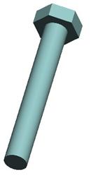
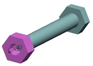
To demonstrate this, open up the Bolt_Nut.asm assembly in your working directory. It will initially look like the following.
Hex_Nut
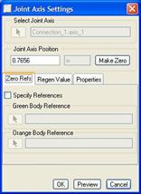
Assemble in the Hex_Nut.prt part into this assembly. When the part comes in, click on the Connections bar to enter into Mechanism constraint mode. Choose the Cylinder constraint, which changes the window into the following.

We only have to pick on two axes, edges or datum curves to line up. Turn on the display of Datum Axes, and then pick on the A_1 axis on both parts. We should see the nut line up with the bolt, and we can see the joint axis symbol for the cylinder connection, as shown below.
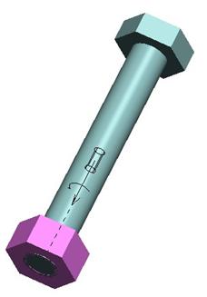
Click on OK to finish this placement, and then go to Applications, Mechanism to enter into mechanism mode.
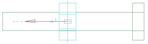
We will start by talking about this joint axis. There are two components to this joint axis, a translation (denoted by the straight arrow that goes down the axis of the part), and a rotation (denoted by the curved arrow).
When we define joint axis settings for this component, we can set each independently. For example, we may have the part located properly along the axis at the “zero” location, but its rotation might not be what we want, therefore, we can change that independently.
We will need to use Query Select (using the right mouse button) to select the one that we want to change.
Joint Axis Settings
Therefore, start by clicking with the right mouse button until just the straight arrow is highlighted in blue. Once it is highlighted, click on it with the left mouse button to select it (in red). Then, use the right mouse button and select Joint Settings. We will get the following window.
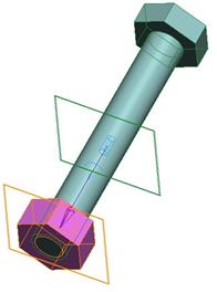
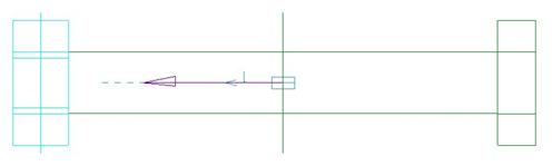
On the assembly, we can see two datum planes highlighted. These are the two references that the distance is measured from, as shown below.
To confirm this, enter a value of “0” in the field, and then go to a RIGHT orientation and turn on “Hidden Line” mode, as shown below.
At this point in time, we will use the zero references tab to figure out what it would take to move the nut all the way to the outside. In this example, a value of 0.9844 will move the nut to the following location.
Once we have the nut at the end, we will click on the Make Zero button, and then turn on the regeneration value to always regenerate at “0”. Click on OK to finish the definition of this joint axis setting and then use Mechanism, Connect to regenerate the assembly. The nut should be sitting at the very outside of the bolt, as shown in the next figure.
Now, we will highlight the entire joint axis, and go into the joint settings to set the rotational component for this cylinder connection. It should already be at the zero value, so we will want to make sure the Regen Value option is set to regenerate the model at “0” degrees. Then, click on OK to finish this setting.
Servo Motors
We can now define the servo motors that will drive this nut onto the bolt at the right rotational and translational speed to move the nut 1 inch in 10 seconds.
To start, create a new servo motor called Translate, and pick on just the straight arrow portion of this joint axis. Once selected, use a Ramp profile where A=0 and B=-0.1. This will allow the motor to translate the nut onto the bolt a value of 1 inch in 10 seconds.
Click on OK to complete this motor. Now, create a second servo motor called Rotate, and pick on the entire joint axis. Once selected, use a Ramp profile again, but this time A=0 and B=-720. This will enable a clockwise rotation of the nut so it completes 7200 degrees in 10 seconds.
Use the graph tool to check both of your motors as you create them to be sure it is set correctly.
Analysis
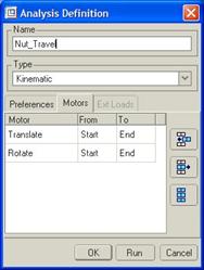
We only have to create a single analysis, however. Therefore, create a new analysis called Nut_Travel, and leave the default time settings alone (we won’t worry about getting the frame rate exactly right).
For the motor tab, make sure both motors are on and run from Start to End in timing, as shown below.
Run the analysis, and you should see the nut rotating and translating simultaneously. Run the playback and create an MPEG movie. To see the result, open up the Nut_Travel1.mpg movie in your directory.
Save and close this assembly.
LESSON SUMMARY
The Cylinder constraint allows a component to translate and rotate about the translation axis. There are two components to the joint axis that can be defined independently. Be sure to use Query Select to pick which part of the joint axis you are going to define.
EXERCISE
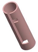
Open up the assembly called Locking_Arm.asm, which should initially look like the following.
We are going to insert the Cyl_Handle.prt component into the assembly so the initial placement will look like the following.
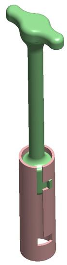
HINT: 36 degrees from the center is where the notch is placed. Use Zero Refs to locate the handle part at the correct translation location.
We are then going to create an analysis to rotate the green part back to the center over a span of 5 seconds, then translate down to the lower notch over 10 seconds, and then rotate the tab on the green part into the notch at the bottom to lock it in place over another 5 second interval.
Therefore, our total animation time will be 20 seconds.