Lesson 9

Lesson Objective: In this lesson, we will continue to learn about the other types of mechanism constraints, starting with the Slider.
USAGE OF SLIDER CONNECTIONS
The slider connection is used to capture one component moving in a straight line. The component is not allowed to rotate in any direction, and can only translate in the single direction specified.
You would use a slider connection to capture motion for:
· Drawer opening and closing
· An object dropping straight down
· Object riding along a straight track
· Any object moving in a straight line
EXAMPLE 1 – CRANK
In this example, we are actually going to see a combination of slider and pin connections to accomplish our assembly motion. Therefore, begin by opening up the assembly called Crank.asm. It will initially look like the following.
We are going to assemble a series of sliders that will ride in the two “T” shaped tracks. At the top of both of these sliders will be a connecting arm that will rotate, causing the two sliders to ride forwards and backwards in their respective tracks.
Therefore, the physical motion of each individual slider component will best be captured using a slider constraint (as each is moving in a single linear direction with no rotations).
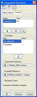
To start, assemble in the Crank_Slider_1.prt part. When the Placement window appears, we are going to click on the Connect tab to get to the Mechanism constraints. It will most likely default to a Pin constraint, so we will need to change that to a Slider, as shown below.
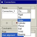
The Placement window looks like the following once you select the Slider option.

We can see that we need to pick two axes or edges to define the Axis Alignment, and we also need to pick to planes or planar surfaces to define the Rotation constraint.
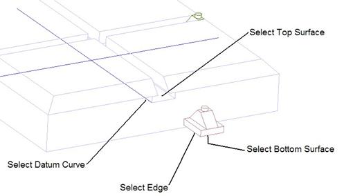
Therefore, we will start by picking the following datum curve and edge for the Axis Alignment constraint.
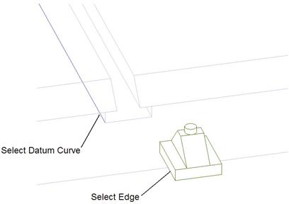
We created a datum curve because we want an edge that runs the entire length of our base part. We could have easily created an axis as well. When we pick these two references, they should automatically line up with each other.
Next we need to define two planes or planar surfaces that will fix the rotation about the selected edges. It is easier to use two surfaces that already intersect the edges that we picked, but you can also use ones that don’t touch and set an offset distance.
In this case, we will pick a surface on each part that the selected edges already lie in, as shown below.
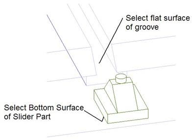
These surfaces should automatically line up. Now, we will click on OK to finish the placement, and then go to Applications, Mechanism to test the movement of this slider.
Slider Joint Axis
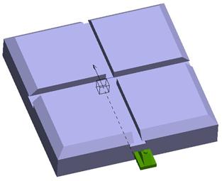
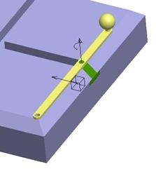
When we enter into Mechanism mode, we can see the joint symbol for a slider constraint (a cube with an arrow sticking out of it, showing the positive direction for motion), as shown in the following figure.
Go to the drag tool ( ![]() ) and select anywhere on the green
slider part. As you move the component, you notice that it will only slide
along the “T” shaped groove, but it is free to leave the confines of the base
part.
) and select anywhere on the green
slider part. As you move the component, you notice that it will only slide
along the “T” shaped groove, but it is free to leave the confines of the base
part.
We can set absolute zero locations for any joint axis, just as we had done for the pin joint. Therefore, click on the Arrow in the joint symbol, hold the right mouse button down, and then select Joint Settings, we will see the familiar window.
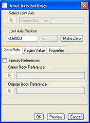
Go ahead and type in 0 in the value field and then press the Enter key. You will notice that the default zero location places the slider in the middle of the assembly. Knowing this, we can now type in a value of -4.375 to get it to go to the edge of the assembly, as shown below.
Once it is at the edge, we will click on the Make Zero button, and then go to the Regen Value tab and enable the regeneration to be at 0. When we click on OK, to exit out of the window, the slider moves back to its last drag position, but we can use Mechanism, Connect to get it to go back to the edge.
Slider 1 Servo Motor
Before we finish bringing in the rest of our components, we
will take a little bit of time to demonstrate a servo motor for moving this
first slider. Therefore, go to the servo motor tools ( ![]() ) and then click on New
to create a new servo motor.
) and then click on New
to create a new servo motor.
Call this servo motor Front_2_Back and pick on the arrow in the joint symbol. For the Profile tab, we will use a Position setting, and use the Ramp magnitude with a value of A=0 and B=0.875, as shown below.
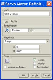
When we click on the graph, we will see the following.
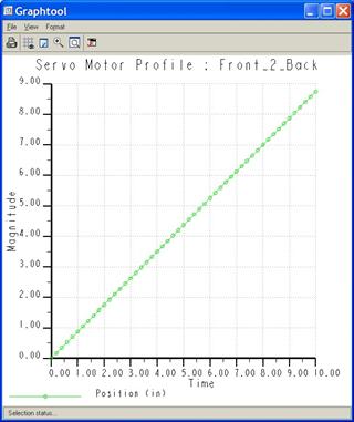
Obviously, the reason we chose 0.875 is because the total distance we want it to go is 8.75 inches (the width of the block minus the width of the slider) in a total of 10 seconds. Therefore our slope is 8.75/10 = 0.875.
Click on OK to finish this servo motor, and then click on Close to exit out of the Servo Motors window. We will now create a simple analysis to check the motion.
Slider 1 Analysis
Click on the Analyses tool ( ![]() ), and then click on New to
create a new analysis. Call this analysis Slider_Move, and accept the
default timing settings. Make sure your slider is still sitting at the front
end of the block. If not, you will need to use Mechanism, Connect to
get it back to its zero position.
), and then click on New to
create a new analysis. Call this analysis Slider_Move, and accept the
default timing settings. Make sure your slider is still sitting at the front
end of the block. If not, you will need to use Mechanism, Connect to
get it back to its zero position.
Then, click on Run, and watch the slider move from the front to the back of the part and then stop. Click on Ok followed by Close to get out of Analysis mode. Then, use Mechanism, Connect to bring the slider back to the starting position.
Now, we will assemble in the second slider component.
Slider 2
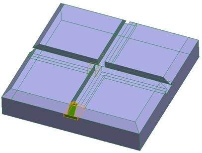
Assemble in the Crank_Slider_2.prt part. When the placement window appears, we are going to use another slider constraint, but this time pick the datum curve that crosses over the one that we used for the last slider part. All other references should be the same, as shown below.
Slider 2 Joint Axis Settings
For this slider, we do not want to control the joint axis settings. We will ultimately have a crank arm installed that will force this second slider into its position based on the location of the first slider.
Slider 2 Servo Motors
As with the joint axis settings for this second slider component, we will not need to create a servo motor. We will be creating one on a future pin constraint to drive the motion of the assembly.
Crank Arm
Therefore, we will assemble in the last component for this assembly, which is the Crank_arm.prt part. We will use two Pin connections to assemble this arm into the existing assembly, as shown below.
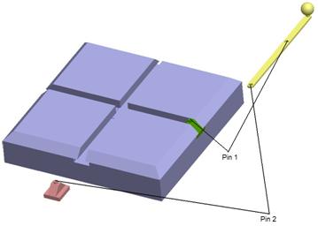
Pin 1
Show datum axes, and select on the two axis shown above. For the translation alignment, pick the top of the green cylinder on the slider part, and the top, flat surface of the yellow arm part.
The placement window will look like the following when this pin is created.
The assembly will look like the following.
Pin 2
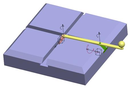
In the placement window, click on the Green “+” button to add another constraint. Then, select the appropriate axes and planar surfaces to finish the placement of this arm. Click on OK to finish the placement, and then go to Applications, Mechanism to view the result. The second slider should snap into place automatically, as shown below.
Animating the Crank
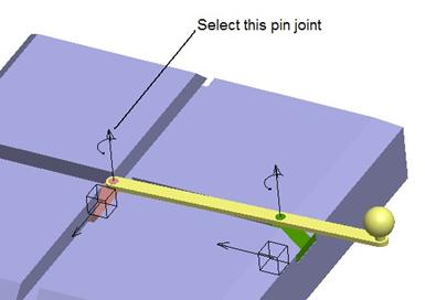
Go to the servo motor tool, and delete the existing servo motor. We will create a new one called Arm_Rotate, and pick on the following pin joint axis.
For the profile, use a Ramp setting with A=0 and B=36 to complete one full rotation. Next, go to the Analysis tool, and delete the existing analysis. Create a new one called Crank_Motion, and accept all defaults. Click on Run and the crank should complete its motion.
When completed, view the playback results. Save and close this assembly when done.
So, why didn’t we use the servo motor on the first slider? We could have, but we might not have gotten a complete 360 degree rotation of the arm. Even if we had modified the servo motor to go forward and then backwards, the arm may have just reversed its original direction, thus only completing a 180 degree rotation before going in reverse.
By using the pin constraint, we could force the arm to rotate a full 360 degrees, and the sliders would follow as necessary to produce the motion. The trick when setting up animations where more than one connection type is used is to understand how the motion will be affected.
Try to chose joint axes that will produce the result in as little effort as possible, as we did in this example.
LESSON SUMMARY
Sliders are used to simulate motion in a single direction (without rotation). You must select two axes, edges, or curves to define the direction, and then two planes or planar surfaces to fix the rotation of the part.
Sliders are typically used in conjunction with other constraints. You can set up servo motors to drive the sliders along their direction.
EXERCISE
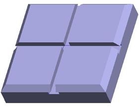
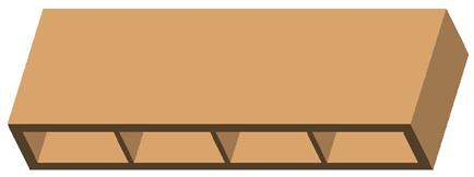
Open up the assembly, entitled Storage_Drawer.asm, which contains a single component, as shown in the next figure.
Assemble in the Drawer.prt file four times using slider constraints. The final assembly in the connected state is shown below.

Then, set up an animation to open each drawer from left to right, and then close them in the reverse order over a 30 second time frame. Each drawer should open up 4 inches.