Lesson 5

Lesson Objective: In this lesson, we will learn how to create snapshots of our assembly at different configurations, and how to use those snapshots for drawings.

TRADITIONAL METHODS
A snapshot is used to capture a particular state of an assembly based on locations of components. To demonstrate snapshots, we will use the Zero_Refs.asm that we saw in an earlier lesson, which looks like the following.
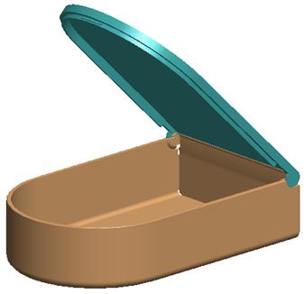
If you remember from Lesson 3, the lid has some limits set at 0 degrees and 90 degrees. At zero degrees, the lid is in the “Closed” state. At 90 degrees, the lid is in the “Fully-Open” state.
Outside of Mechanism mode, you would assemble the lid to the base using a datum plane that could be controlled by an angle. Then, to capture the two different states of the assembly for a drawing, you would need to make a family table, and vary the datum plane from 0 to 90 in two separate instances.
This is okay, but it ends up creating three different models (one generic and two instances). We would rather save family tables for capturing different sizes in a family of parts, and leave the states to Mechanism.
SNAPSHOTS
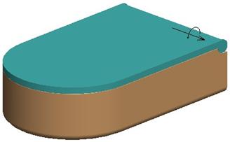
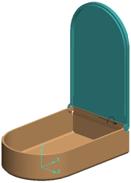
Snapshots are created in the Drag tool. Therefore, we will begin by using Mechanism, Connect and force the lid to close, as shown in the next figure.
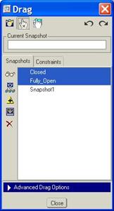
We will go to the Drag tool, and then click on the Take Snapshot icon (the little camera in the upper left corner of the Drag window. When we do this, the word “Snapshot1” appears in the window and in the Current Snapshot field, as shown in the following figure.
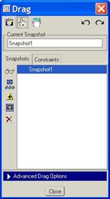
While the snapshot is currently highlighted in blue, we will type in a new name in the Current Snapshot field. We are going to be very careful to remember NOT to use a space in the name, otherwise it will not work for drawing mode.
In the Current Snapshot field, type in Closed as shown below.
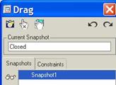
Then, click on the Enter key on the keyboard. The name will update out in the list of available snapshots, as we can see in the following figure.

Now, we are going to click on the Constraints tab and
use the ![]() icon
to set the current pin joint to -90 degrees, as shown below.
icon
to set the current pin joint to -90 degrees, as shown below.
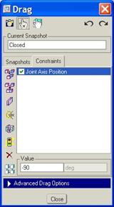
The lid on the model should be in the completely open state, as shown below.
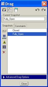
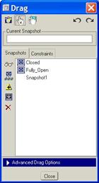
We will now go back to the Snapshot tab, and click on the Take Snapshot icon. When you see the generic snapshot name, type in Fully_Open in the Current Snapshot field and then hit the Enter key on your keyboard.
We will now have two snapshots in our list, as show in the following figure.
We can toggle between snapshots by double-clicking on the
snapshot name in the list, or by highlighting one of them and pressing the Display
Selected Snapshot ( ![]() ) icon. The currently active
snapshot is listed in the upper left corner of the main working window, as
shown below for the Closed snapshot.
) icon. The currently active
snapshot is listed in the upper left corner of the main working window, as
shown below for the Closed snapshot.
![]()
SNAPSHOT TOOLS
The icons in the Snapshots tab will be described in
this section. We already learned about the Display Selected Snapshot
icon ( ![]() ).
).
Borrow Part Position From Other Snapshot ( ![]() )
)
This tool allows you to re-use a position of one or more components within the same assembly that was saved in a different snapshot from the one that is currently active. Start by opening up the lid to a half-way point (approximately 45 degrees).
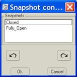
Right now, we have two snapshots (Fully_Open and Closed). In the “Closed” snapshot, the lid’s angle is 0 degrees. We will start by creating a new snapshot, and then select this snapshot in the window. Next, click on the Borrow Part Position icon, and you will see a list of all other snapshots that have been created, as shown in the next figure.
We want the new snapshot to have the lid in the closed position, therefore, we will select on the Closed snapshot. When we pick the snapshot, the working window changes temporarily to reflect this snapshot.
We will then pick on any component on the assembly whose position we want to copy into our new snapshot. Therefore, pick on the lid component, and then click on the middle mouse button to accept it.
Click on OK to complete this command, but don’t do anything else just yet. We will need to click on the Update snapshot command to finish it.
Update Selected Snapshot ( ![]() )
)
This tool is used to update the selected snapshot to reflect the way the model looks on the screen. In this case, we have a snapshot that had the lid at ~45 degrees initially, and we borrowed the closed position of the lid from the Closed snapshot. If we were to preview this snapshot now, it would go back to 45 degrees again. We need to click on the Update icon so that the screen’s current configuration (with the lid closed) is saved as the existing snapshot.
Make Selected Snapshot Available for Drawings ( ![]() )
)
Now that we have some snapshots, we want to use them in our drawing to call out the different states. In order to do that, we first need to select the ones that we want, as shown in the following figure for Closed and Fully_Open.
Once you have the snapshots selected that you wish to use in a drawing, click on the Make Available for Drawings tool, and little camera symbols will appear next to the snapshot names.
These two snapshots can now be used in the drawing.
Delete Selected Snapshot ( ![]() )
)
This is exactly what it sounds like. Select a snapshot that you do not wish to keep (in this case – Snapshot1), and then click on this Delete tool. The snapshot will disappear from the list.
Close out of the Drag window, and save the assembly.
SNAPSHOTS IN DRAWINGS
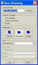
Now that we have two snapshots available for use in drawings, we will create a simple drawing to show how they work. Therefore, create a new drawing called Zero_Refs, and make sure that the Zero_Refs.asm assembly is the model being used, and select a “C” size sheet, as shown below.
When the drawing opens up, change the scale to ½. Next, click on the add general drawing view icon to start to place a new drawing view. In the Drawing View window, select a FRONT orientation, and then click on the View States category.
Check the “Explode components in view” box, and use the pull-down to select the CLOSED snapshot that we took, as shown in the next figure.
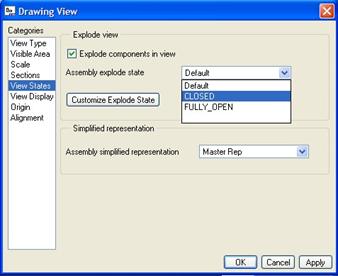
Snapshots are treated as exploded states in drawing mode. That is why we select the Explode Components in View option. Click on OK to complete this view.
Repeat this process to create a second General, Exploded view representing the Fully_Open snapshot state. Our final drawing looks like the next figure.
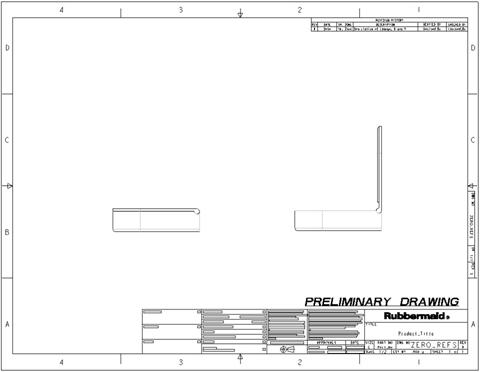
If we were to go look at the models added to this drawing, we would only see the single assembly. If this had been a family table, we would have three different models assigned to this drawing, thus 3x the number of files to have to manage.
If you make a change to one of the snapshots, it automatically updates in the drawing.
LESSON SUMMARY
Snapshots are a great tool to capture different states of a movable assembly. You can then use the snapshots in your drawings to capture these different states on paper.
Snapshots can also be used to determine initial configurations of animations, which will be talked about a little later.
EXERCISE
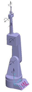
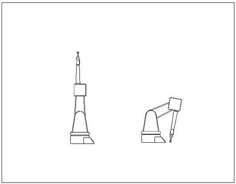
Open up the Robot.asm assembly, and create two different snapshots per the instructions below.
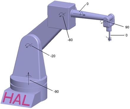
Fully_Extended
In this snapshot, we want to use the following settings for the pin joints shown in the following figure.

The model at these settings looks like the following.
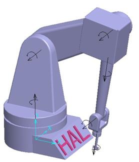
Compressed
For this state, we will be changing two of the settings from the last state to get the following.
The model at this state will look like the following.
Once you have both snapshots, make them available for the drawing, and create a new drawing called Robot.drw that uses an E size sheet with a scale of ¼. Create two general views, one for each state, as shown in the following figure.
Use a Left orientation for both of these views. Once you are done, save and close the drawing and the assembly.