Lesson 4

Lesson Objective: In this lesson, we will look at the dragging capability in a lot more detail – learn about point and body drags, as well as drag constraints.

POINT DRAG
The most common method for dragging is using the point drag. The way the Point Drag works is the location on the model where you pick is the point at which you are dragging it. Imagine a small handle at the exact location where you pick on the model.
Therefore, if you imagine a wheel spinning, you may have more control over the drag by grabbing out on the rubber tire itself (further away from the center of the tire), but you will have a harder time making it spin fast. The closer to the center you pick, the faster you can make the tire spin without wrecking your wrist or elbow using your mouse.
When you enter into drag mode, by clicking on the ![]() icon, you get the
following window.
icon, you get the
following window.
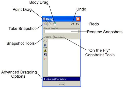
At the top, the Point Drag icon is selected by default. This is the one we have been using, and it will be the first one that we go into more detail about.
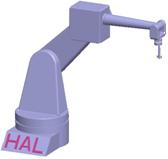
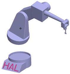
To demonstrate this functionality, open up the Robot.asm assembly that we have been working with in the last two lessons. It will initially look like the following (assuming you have completed the exercises from the last two lessons.)
To begin, go to Applications, Mechanism from the menu bar to re-enter Mechanism mode. If you remember from the previous lessons, we used the point drag to try out our different pin connections, but we had problems with the entire assembly moving at once. To check out each connection individually, we will use some constraints in the drag window.
LOCK/UNLOCK BODIES
When you are dragging around bodies in Mechanism, as we have with this Robot assembly, you can force a movable body to lock into its current placement for the duration of a drag operation, and unlock it again once you want to move it.
The Lock/Unlock Body constraint in the drag window only lasts while you are in the drag window. Once you close out of the drag window, this temporary condition is removed.
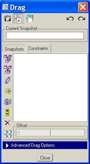
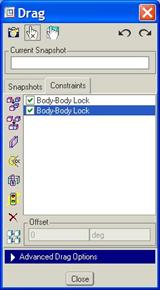
To demonstrate this, go into the drag window for the robot assembly. Click on the Constraints tab, and the window will look like the following.
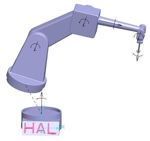
The icons down the left side are specifically for the Constraints tab. We will begin by clicking out on our model on the Robot_3 component, in the location shown in the following figure.
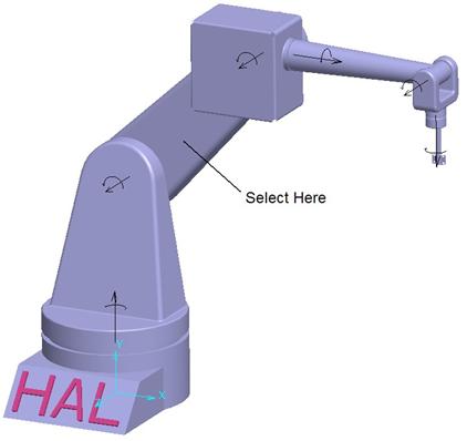
As you move your mouse around, you will notice two things. The first is that all other components that came after this arm (Robot_4, Robot_5, Robot_6 and Robot_7) are not independently moving. This is because of where we picked. The second is that while we can rotate Robot_3 around, the Robot_2 component also rotates. Click on the middle mouse button to cancel the drag and the assembly should jump back to its original position.
To isolate just the movement of Robot_3 and anything assembled later, we will need to lock the movement of Robot_2.
Ground Part
Before we lock Robot_2, let’s first talk about the ground part. Each assembly in Mechanism contains at least one ground part. This is a part that does not have any open degrees of freedom. In this case, Robot_1 (the one with the word “HAL” on it), is not free to move. It is considered the “Ground” part. All other components have a pin connection on them, allowing them to move. These are called “Bodies”.
When you lock a body, you must specify one component that acts as a ground (even if it is not the actual ground part), and one that is locked to it. In this case, to lock the movement of Robot_2, we would actually use the real ground part (Robot_1) as the ground, and then lock Robot_2 to it in whatever position it is in.
Lock Robot_2
In the Constraints portion of the drag window, click
on the ![]() icon.
In the message window, you are prompted to select a ground part. NOTE: If you
are picking the actual ground part that is in the assembly, you can just use
the middle mouse button at this time. We will actually select Robot_1
by picking on it to get in the habit of selecting a ground part.
icon.
In the message window, you are prompted to select a ground part. NOTE: If you
are picking the actual ground part that is in the assembly, you can just use
the middle mouse button at this time. We will actually select Robot_1
by picking on it to get in the habit of selecting a ground part.
Once you select Robot_1, you are asked to select the body that you are locking. In this case, select the Robot_2 component by picking anywhere on it. At this time, both Robot_1 and Robot_2 should be highlighted in red on your assembly.
You can continue to pick more parts that will be locked, but we are done, so we will click on the middle mouse button to accept these two selected parts. In the constraints window, you will see the following.

When you highlight the “Body-Body Lock” entry, the model will show you the components affected by this lock. In this case, it makes the ground part (Robot_1) highlight in green, while the locked parts (Robot_2) are highlighted in a dark red. The check mark indicates that this lock is currently active.
Now, click on the Point Drag icon at the top of this window (if it is not already selected) and pick again on the Robot_3 component in the same location as we did before. This time, you will be able to move the arm, but the lower component (Robot_2) does not move.
Now, suppose we wanted to lock Robot_3 to see how Robot_4 and the rest of the assembled components behave. In the constraints window, click on the Lock/Unlock Bodies icon again, and this time select Robot_2 for the ground, and then select Robot_3, followed by the middle mouse button.
You should now have two “Body-Body Lock” entries in the drag window, as shown in the next figure.
Click on the Point Drag icon again, and this time pick anywhere on Robot_4 to drag it. When you are done, click on the middle mouse button to cancel the drag, and then close the Drag window.
Re-open the Drag window, return to the Constraints tab, and you will notice that the lock conditions are no longer there – remember they are only temporary.
ALIGN, MATE, ORIENT CONSTRAINTS
In addition to being able to lock bodies in place, you can also affect the behavior of certain bodies during a drag using Align, Mate or Orient constraints.
An Align constraint, activated with the ![]() icon in the Constraints
tab of the Drag window, allows you to specify two planes or planar
surfaces on two different bodies to line up with each other. Since this is
very similar to the next constraint (Mate) we will wait and demonstrate
that one.
icon in the Constraints
tab of the Drag window, allows you to specify two planes or planar
surfaces on two different bodies to line up with each other. Since this is
very similar to the next constraint (Mate) we will wait and demonstrate
that one.
A Mate constraint, activated with the ![]() icon in the Constraints
tab of the Drag window, allows you to specify two planes or planar
surfaces on two different bodies to touch each other. We will demonstrate this
now.
icon in the Constraints
tab of the Drag window, allows you to specify two planes or planar
surfaces on two different bodies to touch each other. We will demonstrate this
now.
In the Robot assembly, go back into the Drag
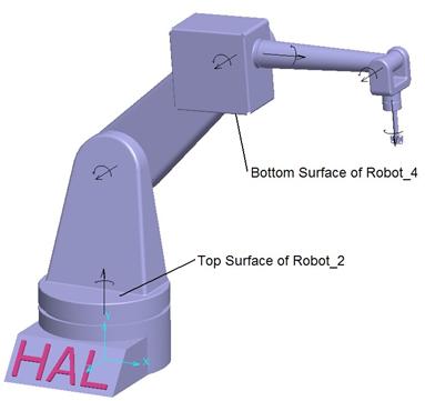
command. Once inside, click on the Constraints tab, followed by the ![]() icon. We are
prompted to select two planes or planar surfaces to mate. We will select the
ones shown in the next figure.
icon. We are
prompted to select two planes or planar surfaces to mate. We will select the
ones shown in the next figure.
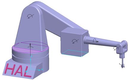
When we do this, the bottom surface of Robot_4 snaps down to line up and face the top surface of Robot_2, as shown in the next figure.
Now click on the Point Drag icon and try picking on Robot_4 to move it. Notice that Robot_2 is free to rotate, but Robot_3 and Robot_4 are locked into place because it is trying to satisfy this condition. Click with the middle mouse button to cancel out of the drag. Close the drag window if it is still open.
Orient
The orient constraint uses the ![]() icon in the Constraints tab
on the Drag window. It forces two planes or planar surfaces to be
parallel with each other and face in the same direction.
icon in the Constraints tab
on the Drag window. It forces two planes or planar surfaces to be
parallel with each other and face in the same direction.
NOTE: You can also enter a value other than 0 for the offset for this constraint to set a certain angle between surfaces.
We will demonstrate this now. Go back into the Drag
tool for the robot assembly. Click on the Constraints tab, and then
click on the ![]() icon.
Select the two surfaces shown below.
icon.
Select the two surfaces shown below.
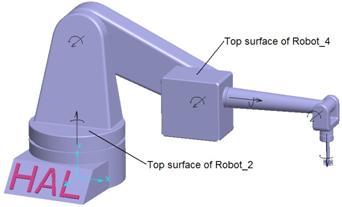
You will get an entry for Plane-Plane Orient in the Drag window. Click on the Point Drag icon at the top of the Drag window, and pick anywhere on Robot_3 to move the assembly. Notice that as you rotate the arm up and down, the top surface of Robot_4 maintains a parallel condition with the top surface of Robot_2. Click anywhere to stop the drag, and then close out of the drag window.
Use Mechanism, Connect to return the assembly back to the zero reference state, and then save the assembly.
JOINT AXIS SETTING CONSTRAINT
Within the drag constraints, there is a Joint Axis Setting icon, which looks like the following.
![]()
This tool is very useful when you want to set a joint axis to an exact value, and not have it revert back once you get out of the joint axis settings window (like we have seen in the past). We will demonstrate that with the robot assembly.
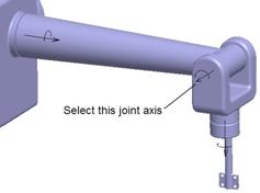
Click on the Drag tool, and once inside, click on the
Constraints tab. Click on the ![]() icon and then pick on the joint axis
indicated in the following figure.
icon and then pick on the joint axis
indicated in the following figure.
Once you select this joint axis, you will see the following in the Drag window.
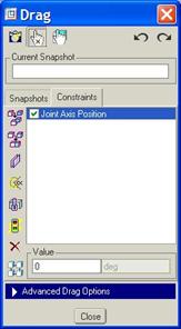
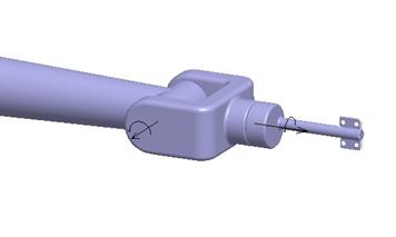
At the bottom of the window, you can see a field entitled Value. The value is currently at zero. Type in 90 and then hit the enter key on your keyboard. You should see the joint update, as shown below.
When you close out of the Drag window, it will remain at its current position until you move it again, or you connect up the assembly (regenerate). The advantage of using this can be seen before setting up limits.
Suppose you hadn’t set up any of the limits for these joint axes. You would start by resetting the zero values where needed, and then tell each joint to regenerate at the zero value. Connect up the assembly to get your starting point.
Next, you would come into the drag window, go to the Constraints tab and add each joint axis using this tool. Your window would look like the following for this robot assembly.
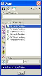
You could then go through each one and test values until you found the total distance you wanted it to travel. Then go back later and set your limits. When you select on one of the entries in the figure above, it highlights the joint axis on the model itself, so you can tell which one is which.
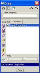
DISABLE/ENABLE CONNECTION
Re-connect your robot assembly to get it back to its starting point at all zero references.
This topic is one you should be careful using, because it acts almost like you went back and deleted the pin connection, causing it to be completely “packaged”. To demonstrate this, go to the drag tool, then to the Constraints tab. In the constraints tab, click on the following icon.
![]()
You are prompted to pick one or more constraints to disable. We are going to select the pin constraint that was created when assembling Robot_2 (at the very bottom of our assembly). Once it is selected, click on the middle mouse button to accept our selection. You will see the following in the Drag window.
Click on the Point Drag icon at the top, and then pick anywhere on Robot_2 and move it. Notice how it gets completely disconnected from the base?
When you click to place the Robot_2 component in a new location (away from the base), you will get a dashed line that indicates where it is really connected to, as shown in the following figure.
When you close out of the drag window, the assembly will re-connect itself.
DELETE CONSTRAINT and ASSEMBLE
The last two icons in the Constraints area are Delete
Constraint ( ![]() ) and Assemble using Current
Constraints (
) and Assemble using Current
Constraints ( ![]() ).
).
Delete Constraint
This is pretty self-explanatory. If you highlight a constraint in the window and then click on this icon, it deletes the constraint. In the case of a Disable constraint, the assembly will reconnect the components with dashed lines between them.
Assemble using Current Constraints
In Mechanism Mode, this icon really doesn’t do anything. It is designed to work with Design Animation – another module that works closely with Mechanism.
ADVANCED DRAG OPTIONS
At the bottom of the drag window, there is a blue bar entitled Advanced Drag Options. Clicking on the white arrow at the left of this bar will expand it to show the following.
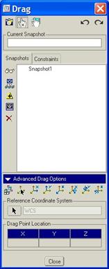
The different elements of this portion are described in the following figure.
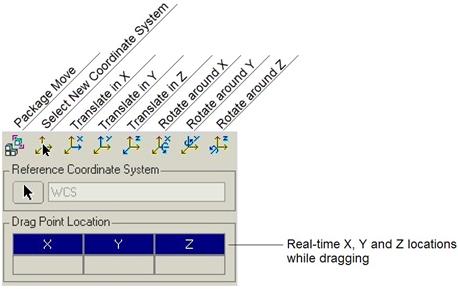
A Package Move ignores all current drag constraints that have been set, and behaves just like a move operation when assembling into a regular assembly.
The Select New Coordinate System allows you to specify a different datum coordinate system in the model to control where your X, Y, and Z translations and rotations originate from.
The rest of the icons allow you to move a body in any of the six degrees of freedom with respect to the selected coordinate system.
At the bottom, the Drag Point Location shows you the exact X, Y and Z location of the point where you picked to perform the drag with respect to the selected coordinate system.
BODY DRAG
At the top of the Drag window, there is another drag icon, called Body Drag (if you recall from the very first figure in this lesson). This allows you to pick on a component and move it in its current orientation. Any components connected to it will move, but the selected component will not rotate or change its orientation.
To see this, go back to the robot assembly and run Mechanism, Connect to get back to a starting point. Next, click on the Body Drag icon, and select Robot_5. As you drag this, you will notice that Robot_2 and Robot_3 move, but Robot_5 stays in its exact orientation (horizontal), which causes Robot_4, Robot_6 and Robot_7 to keep their current positions too.
So, why can’t we select Robot_2 or Robot_3 in this example using “Body Drag”? We can, but they won’t do anything. Robot_2 is connected to the ground, and everything else is connected to it. Therefore, it can’t really move on its own and keep the same orientation.
The same thing is true for Robot_3. To maintain its exact orientation, Robot_2 can not move, and thus, the whole assembly can not move. The rest of the components (Robot_4 through Robot_7) can be dragged with this tool.
Try it yourself. When you are done, close out of the drag window, save and close the assembly.
LESSON SUMMARY
Dragging your assembly allows you to check whether your connections are working. It is also used to create positions of the assembly that can be used to create snapshots (next lesson).
While dragging, you can add temporary constraints, such as aligning two surfaces, or locking/unlocking bodies. Once you close out of the drag command, these constraints go away.
EXERCISE
Open up the assembly called Mirror.asm. It will initially look like the following.

Go to mechanism mode (Applications, Mechanism) and try dragging the entire assembly around first without adding any constraints. Return to the original orientation using Mechanism, Connect.
Next, try to isolate only the movement of the arms in the middle by locking the hinges at the base, as well as the mirror at the top. Return to the original orientation when done.
Finally, try forcing the middle arms to be parallel to the bottom arms while dragging. Return to the original orientation when done.
Save and close the assembly.