Lesson 3

Lesson Objective: In this lesson, we will look at the joint axis settings in more detail using the pin constraint that we have already learned. We will learn about limits, regeneration settings, and zero references.

ZERO REFERENCES
In the last lesson, we learned how to identify the default zero location of a pin joint axis. We also learned how to type in any angle to see the pin joint update. We even went one step further and took a non-zero location (45 degrees, for example) and turn it into the new global zero location for that pin joint (using the Make Zero button).
In this lesson, we will learn how to use our surrounding geometry to define the zero location. Therefore, open up the assembly entitled Zero_Refs.asm, which will look like the following.
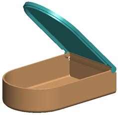
This assembly consists of a base and a lid, which is attached using a pin connection. We are going to start by investigating where the current zero reference is for the pin joint. Therefore, go to Applications, Mechanism to activate mechanism mode.
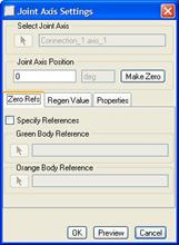
Next, click on the pin joint symbol on the model so it becomes highlighted in red. Finally, right mouse click and select Joint Settings. This will bring up the following window.
We can see that the lid is currently at the zero location, but we want the lid to be completely closed when it is at zero. Instead of trying different values in the field until we get one that looks like it mates the lid with the base (which we may never get an exact value), we are going to pick on references in the part to control this.
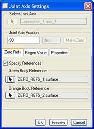
In the middle of the Joint Axis Settings window, we see three tabs, entitled Zero Refs, Regen Value and Properties. The Zero Refs tab is already selected, which is the one that we want.
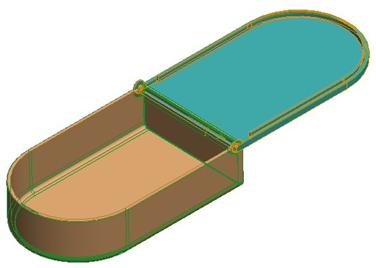
Before we do anything, we are going to look at our model, which currently has one of the parts highlighted in green, while the other is highlighted in orange, as shown below.
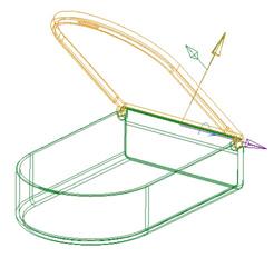
From the above figure, we can see that the base part (Zero_Refs_1.prt) is our green part, while the lid (Zero_Refs_2.prt) is our orange part. In the window, we can see that we are going to select a reference for each of these models.
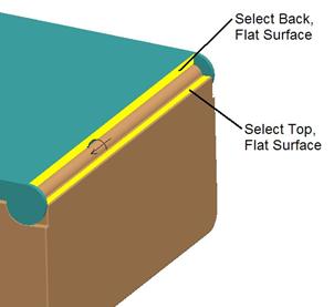
Therefore, click in the little check box entitled Specify References and then you will be prompted to select the reference on the orange part. We are going to pick the flat bottom of the rim that we want to mate up with the base part.
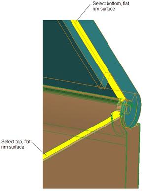
When prompted to select the reference on the green part, we are going to select the top, flat rim of the base part. The two references are shown below (highlighted in yellow to make it easier to see them).
Once both references are selected, we will now look back into our joint settings window. We can see the angle value between them (which is currently 135 degrees). Therefore, we know that 45 degrees separates our lid and base in its current position. We will type in “0” and this is what we see.
This is the opposite of what we want, so we will change the value to 180, and this is our result.
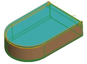
This is exactly what we want. Now, we might be tempted to click on the Make Zero button, but it is not available at this time. Therefore, if we want this to be considered the absolute zero, we can uncheck the Select References box, and then click on Make Zero. Now, our zero value is set with the lid closed.
Click on OK once you have made this the new global zero reference. What do you notice? The lid goes back to its open state. We will address this in the next section.
Save the assembly for now.
REGEN VALUE
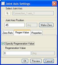
Go back to the joint axis settings for the pin joint again. In the middle, click on the second tab entitled Regen Value. This will look like the following figure.
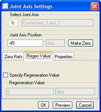
We can see that our joint axis is currently at -45 degrees. Down in the Regen Value area, we will click on the Specify Regeneration Value check box, and then keep the default of 0 in the Regeneration Value field, as shown below.
What we are doing is telling Pro/ENGINEER that every time we regenerate this assembly, we want this pin joint to go back to its zero degree value, which will cause it to close. Click on OK. Your assembly may or may not automatically close. If it does not, regenerate your assembly and it will close, as shown in the next figure. To regenerate, you will need to go back to standard mode (Applications, Standard).
Save the assembly for now.
PROPERTIES
There is one more thing we can define in the joint axis settings for this pin connection, and that is the properties – which allows you to control the limits of the motion of the connection.
IMPORTANT: Limits should only be set to control the range of motion while dragging. You should get in the habit of turning them off when you are ready to animate your mechanism, unless you need to simulate specific forces that arise from bodies hitting each other, where the limit assumes an impact location.
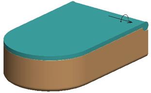
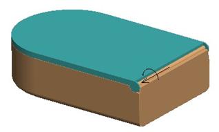
To demonstrate the limits of this part, we will first rotate the assembly so we are looking at the back where it is hinged, as shown below.
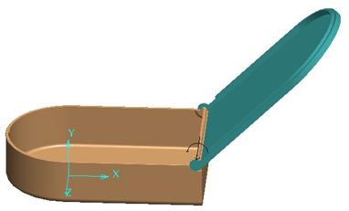
We will begin by clicking on the drag icon ( ![]() ) and open up the lid past
the vertical position, as shown below.
) and open up the lid past
the vertical position, as shown below.
Click on Close to get out of the drag window. The lid should remain open. Return to standard mode (Applications, Standard), and then run a global interference check using Analysis, Model Analysis, Global Interference, Compute. You should see an interference all along the back edge of the lid, as shown in the next figure.
Therefore, we know we can’t go too far, or we will have interference. This assembly was designed so that at 90 degrees, the back of the lid rests on the back of the base. But, suppose, we didn’t know that it was 90 degrees. How can we find out how far we can go?
We will use the Zero References again to find out the angle that we need to set as our limit. Therefore, go back into mechanism mode using Applications, Mechanism. Go back into the joint axis settings for the pin joint, and make sure you are on the first tab, entitled “Zero Refs”. Start by typing in a value of “0” in the field at the top to close the lid.
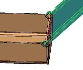
Next, click in the check box to “select references”, and then pick the following two entities (shown highlighted in yellow in the next figure).
When we do this, our joint axis settings window looks like the following figure.
From this window, we can see that the angle between these two surfaces when the lid is closed is -90 degrees. Therefore, we can go from 0 to -90 degrees before the lid will start to interfere with the base at the back.
Click on Cancel in this window to deselect the references that we just selected. IMPORTANT: If you click on OK, it now sets the new zero location differently than what it was before.
When we click on Cancel the lid goes back to the last location we dragged it to. Therefore regenerate the assembly (in standard mode) to get it to go back to zero (lid closed).
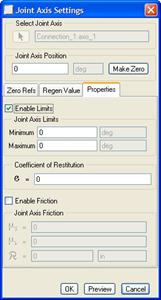
Return to mechanism mode and then go back to the joint axis settings for this joint one more time, and this time click on the Properties tab, which will look like the following.
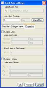
Start by clicking in the checkbox entitled Enable Limits. This will make the other fields available, as shown in the next figure.
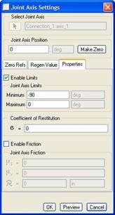
When setting joint axis limits, always remember that negative values are smaller than positive values, and therefore the smallest number is placed in the “Minimum” field. Therefore, we are going to enter -90 in the Minimum field, and 0 in the Maximum field, as shown in the following figure.
IMPORTANT: The maximum range for limits is 180 degrees. For example, if you are starting at -20 degrees, you can go to 160 degrees for a maximum. To simulate a range over 180 degrees, you will be using servo motors (described in a later lesson).
Coefficient of Restitution
The following excerpt comes from the online help, and best describes what this field is for:
“If you want to simulate impact forces for your cam-follower connection, slot-follower connection, or joint, specify a value for the coefficient of restitution. The coefficient of restitution is defined as the ratio of the velocity of two entities after and before a collision. Typical coefficients of restitution can be found in engineering textbooks, or from empirical studies. Coefficients of restitution depend upon factors including material properties, body geometry, and impact velocity. Applying a coefficient of restitution to your mechanism is a way to simulate non-rigid properties in a rigid body calculation.
For example, a perfectly elastic collision has a coefficient of restitution of 1. A perfectly inelastic collision has a coefficient of restitution of 0. A rubber ball has a relatively high coefficient of restitution. A wet lump of clay has a value very close to 0.”
For our purposes, we are going to leave this with a value of 0, and then click on OK to finish out of this window.
Use the drag tool and try moving your lid. Notice that it will stop at the closed and 90 degree positions. This is simulating a realistic range of motion for this assembly.
CONNECT
In Mechanism mode, you can test the robustness of your mechanism using Mechanism, Connect. What this will do is set any joint axes to their regeneration values, checks the body definitions to make sure you don’t have three different bodies used for a single constraint, etc.
This is one way to get out of having to go back to standard mode to regenerate the model. To demonstrate this, drag the lid back to an arbitrary location between its limits. Then, go to Mechanism, Connect. The following window appears.
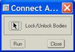
With this window, you can specify certain components (bodies) that are immune to the check. In our case, we will let all of the bodies get checked. Therefore, click on Run, and then we will see the following.
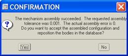
At the same time, the lid closed, because it set the pin joint to its regeneration value of “0 degrees”. Since it changed the current configuration of the assembly, it gives you the choice to accept the change or reject it. To accept it, click on Yes. Our assembly is back at the closed state.
LESSON SUMMARY
When defining mechanism constraints, you should always look at the joint axis settings for each constraint. You can control the absolute zero location for the joint, as well as limits that the joint can travel.
For consistency, you should set your regeneration value so that each time you regenerate or connect up the assembly, it goes back to the standard configuration.
Use existing references on the models to find out where your zero location is, or how far you can go for a limit setting.
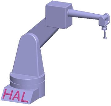
EXERCISE
Open up the Robot.asm assembly again. If you recall from the last exercise, we created six different pin constraints. For consistency, we’ll refer to them in the following order.
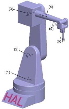
For this robot, we want to reset the zero value for joint #2 to be at the current -45 degree value. We also want to reset the zero value for joint #3 to be at the current 45 degree value. Then, set the joint axis settings for limits and regeneration values as the following:
|
Joint Axis # |
Regeneration Value |
Minimum Limit |
Maximum Limit |
|
1 |
0 |
-90 |
90 |
|
2 |
0 |
-90 |
45 |
|
3 |
0 |
-90 |
90 |
|
4 |
0 |
-90 |
90 |
|
5 |
0 |
0 |
180 |
|
6 |
0 |
-90 |
90 |
Once you are done, try dragging your assembly around to see where everything stops. When we run a Mechanism, Connect at the very end, and return to standard mode, we should have the following assembly configuration.