Lesson 2

Lesson Objective: In this lesson, we will learn all about the pin connection, and get introduced to the concept of dragging a mechanism to make sure it is working.
USAGE OF PIN CONNECTION
The pin connection is used to capture one component rotating with respect to another component through a shared axis or edge. You would use a pin constraint to capture motion for:
· Lid that opens on a hinge
· Door that swings open
· Wheel that turns
· Rotating components (such as a desk chair)
· Any hinged object (except living hinges – can’t capture these in Mechanism and still maintain a physical connection between the two components)
EXAMPLE – FAN ASSEMBLY
Assembling the Blades using Connections
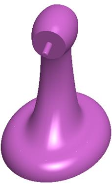
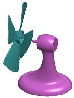
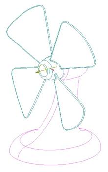
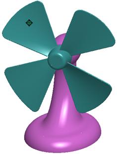
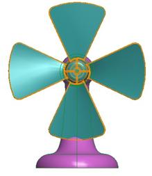
To demonstrate a simple pin connection, we will create a fan. Make sure your working directory is set to c:\Data\MDXTrain and open up the assembly entitled fan.asm. It should contain a single part, and look like the following.
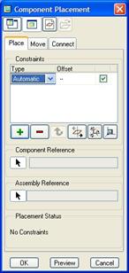
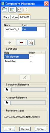
We will start by clicking on the assemble component icon, and select the fan_blades.prt component in the File Open window. When we do this, the Component Placement window appears, showing us the traditional placement constraint box, as shown at the top of the next page.
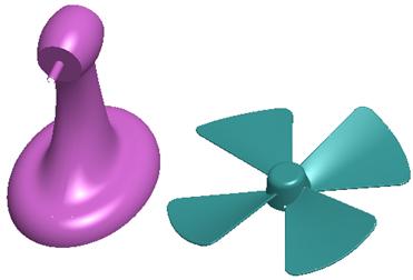
In the working window, we can see both components.
Since the fan blades rotate about the shaft on the fan body, we will use a pin constraint to capture this motion. Therefore, we will begin by clicking on the Connect tab to access Mechanism constraints, as shown in the next figure.
If the connection type is not Pin already, then change it over to PIN. We can see that we are asked to select two axes to align. Therefore, turn on the view of datum axes, and select the FAN_AXIS and BLADE_AXIS axes from the two components. The blade component will line up with the body component along these axes, but the blade may be embedded within the body, as shown below.
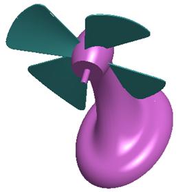
Use Ctrl-Alt and the Right Mouse Button (RMB) to move the component forward, and away from the body, as shown in the next figure.
In the Component Placement window, we are now asked to select two datum planes or planar surfaces to fix the translation. These planes must be perpendicular to the already selected axes to fix the translation along the axes. Therefore, select the small flat surface on the end of the blade part, as shown below.
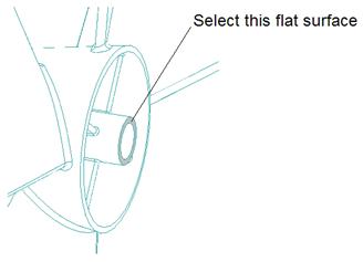
Then rotate the model and select the large flat surface of the body part shown in the next figure.
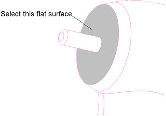
The placement definition should be complete, as the blade part now rests up against the body part. You will see an arrow with a curved arrow around it, as shown below.
This is the joint axis for a pin connection. We will click on OK from the placement window to finish out of this placement. Once we are out of the placement window, the joint axis symbol disappears from the model.
In the model tree, we can see that the fan_blades component is packaged (little white square to the left of the name).
Save this assembly.
Dragging the Blades around
Now that we have our blades assembled using a pin connection, we will use the drag functionality to manually rotate our blades. Therefore, we will need to get into Mechanism mode by going to Applications, Mechanism. When we do this, the joint axis will appear on the model again, and we will see new icons at the right of our working window.
We will start by clicking on the Drag icon, which looks like the following:
![]()
When we do this, we get a new window that appears, as shown in the following figure.
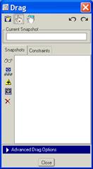
We will go into more detail about this drag window in a later lesson. For now, we will simply pick on the blade part over one of the four blades. Where we pick, we will see a little diamond-shaped symbol, and our fan will begin to rotate as we move our mouse cursor around, as shown below.
Click with the left mouse button to stop the drag command, then close the Drag window. The diamond-shaped symbol disappears, and the joint axis symbol reappears.
Pin Joint Axis Settings
Now we will take a look at the joint axis settings for a pin connection. To do this, we will place our mouse cursor over the joint axis symbol so it highlights, then click once to select it. Once selected, hold down the right mouse button and select Joint Settings.
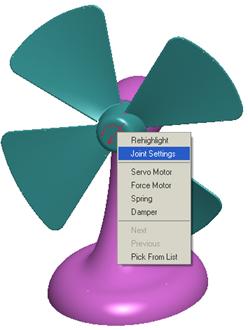
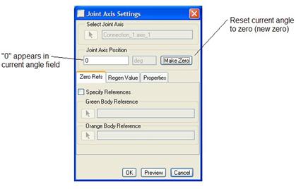
A new window will appear, as shown in the following figure.
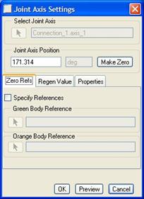
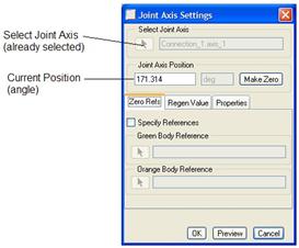
At the top of this window, you can select a joint axis if we hadn’t already selected one. Just below this, there is a field that shows the current position of the joint axis. In this case, it shows the current angle at which the blade is sitting (171.314 degrees). This is shown in the next figure.
Rotate your model to a FRONT view, and then type in a value of “0” in the field. The blade part will rotate back to zero degrees based on how it was originally assembled. It will look like the following.

Now, try typing in a value of “45” in the field. You will see the following.
Suppose you want this orientation to be the absolute zero location. All you have to do is click on the Make Zero button in the window, and this will now be the zero location for all time, as shown below.
We will go into more detail about this joint axis settings window in later lessons. For now, click on OK in this window. You may notice that your blade part rotates back to the angle it was in before we went into the settings. This is okay, because our new zero location is still saved, we just never specified that we wanted it to stay at zero. We will see this a little later.
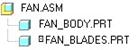
For now, look at your model tree. Expand the item called CONNECTIONS, and then continue to expand all the items below this until you see the following.
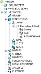
From this figure, we can see that we have one connection, called Connection_1(FAN). We will get some information out of this model tree for this joint axis. First, the Ground item shows us the component that remains fixed in the assembly. Each assembly has at least one component that is not free to move, in this case the FAN_BODY.PRT component. If you were to click on this item in the model tree, you would see the fan_body.prt component highlight on the model.
The body1 item shows the other component used in this joint axis, the fan_blade.prt component.
Finally, the ROTATION AXIS line represents the joint axis itself. If you were to right click on this item, you would see the Joint Settings menu item, which would bring you back into the definition for this joint axis.
Save and close this assembly.
LESSON SUMMARY
Use a pin connection to simulate components that rotate about an axis. Define an axis alignment and a translational constraint for this connection.
Define the zero location for your joint axes to ensure you know where your starting location is.
Drag your components to verify that the connection is set up the way you want it.
EXERCISE
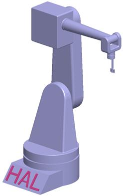
Open up the assembly entitled Robot. It will initially only contain one component (Robot_1.prt), as shown below.

We are going to add the rest of the components (Robot_2.prt, Robot_3.prt, Robot_4.prt, Robot_5.prt, Robot_6.prt and Robot_7.prt) to get the completed robot assembly, shown in the next figure.
Be sure to use Pin connections to assemble each of these robot pieces. Turn on the display of datum axes to see which axes to use.
IMPORTANT: Each pin connection requires two axes/edges and two planes/planar surfaces. You must remember to only select between two components. For example, when you assemble Robot_3.prt, you will have Robot_1 and Robot_2 already in the model. You should use an axis and a plane on Robot_3 and an axis and a plane on Robot_2. You should not end up using Robot_1.
After you assemble each component, go to Applications, Mechanism and drag the component to see the assembly update. While dragging, click on the Middle Mouse Button to return to the original configuration, do NOT click with the left mouse button to place the assembly in a new orientation. If you accidentally click with the left mouse button, use the upper right “Undo” arrow in the drag window to return to the original configuration.