|

Lesson Objective: In this lesson, we will introduce the ISDX module, talk about the importance of free-form design and its fit with traditional Pro/ENGINEER design elements.
“ART TO PART”
When Pro/ENGINEER burst on the scene, it was a revolutionary way to design mechanical components. The biggest difference between Pro/ENGINEER and its competition at the time was the way in which you approached solid modeling.
AutoCAD had been around for years, but was limited to two-dimensional design. Other three-dimensional modeling packages used a “Boolean” approach to design. In other words, you created primitives (spheres, rectangles, cylinders, rounds, chamfers, holes, etc.) and either used them to add material or cut-away material.
Pro/ENGINEER’s approach to modeling was to sketch a two-dimensional profile and then perform an operation to that profile, such as extrude, revolve, sweep, blend, etc. It also had some “primitive” sort of features, such as rounds, chamfers, shell, etc. that did not require a two-dimensional sketch. These were referred to as “Pick and Place” features.
By allowing the user to sketch a profile, it opened up the ability to deal with more complex shapes and create more complicated products in less features than a traditional Boolean system.
Regardless of the method by which you created mechanical components, most (if not all) of these systems required dimensional information to define the size and location of the features. For a design that is ultimately used in manufacturing, this is critical. Without dimensions, manufacturers would not be able to make the parts.
A New Era
With the widespread use of CNC (Computer Numerically Controlled) Machining tools, the ability to design complex products with less emphasis on dimensions became easier. CNC tools use X, Y, and Z coordinate data to define the shape, so any volume in 3D space could be calculated without using a single dimension.
When this happened, there became a greater emphasis on the look of the product than merely the function of the product. Aesthetics in design gave birth to the distinction between industrial design and traditional engineering. This was most evident in the automotive industry, as concept cars started to have more curves and bubbles than angles and straight lines.
There was still a major division between the “Art” and “Part” of design. Artists created hand sketches, or some minimal electronic sketches that defined the ultimate look of the product, but it was left up to the engineer to bring this idea down to something that could be manufactured and hold up to the daily use of the product.
Alias|Wavefront
As computer technology became better, so did the ability for people to capture realistic renderings of objects. In the entertainment industry, Alias|Wavefront has been a leader in creating computer animations that simulate realistic places and objects. Many of the science fiction and anime productions today take advantage of this technology to create breathtaking imagery and amazing realism, mixing real-life footage with computer-generated sequences and events.
In the manufacturing industry, companies can produce startling images of products months or even years before the product is ever released. The problem has always been the “Art to Part” aspect of using the technology.
Data Transfer
With Industrial Designers using Alias|Wavefront, and Product Engineers using Pro/ENGINEER, it is required that some data transfer occur. There are a number of national and international data exchange formats available (IGES, STEP, VDA, DXF, etc.) and there is even a special Alias-Pro exchange format (Granite) that exists. The problem, however, is on the Alias side.
A model in Alias|Wavefront is made up of edges and surfaces. There is no solid volume in the renderings that we create. Because a solid volume is not required, the accuracy of the edge definitions is also not required. You can create two surfaces that “appear” to touch, but actually have tiny gaps. When you create a rendering of the model, you still get the result you are looking for.
When you send this model to Pro/ENGINEER (through any of the exchange formats), you end up with a surface model in Pro/E. By default, Pro/ENGINEER tries to look for a completely closed surface model in which to automatically generate a solid model. When it encounters a single gap, it is unable to do this.
The Product Engineer is then forced to attempt a surface fix of the part (which could be very simple, very difficult or impossible), or discard the imported geometry and start a new model from scratch.
If the Product Engineer decides to use the imported geometry, in any form, then the ability to make dimensional or shape changes drastically diminishes, since the imported geometry can not be modified. Going back to Alias to modify this does not update the Pro/ENGINEER imported geometry.
Finally, in Alias, you must be conscious of your global coordinate system, otherwise, the geometry, when imported into Pro/ENGINEER lies in an arbitrary location, away from the default datum planes and other geometry used to create the solid model. This makes it very difficult for the Product Engineer to use this geometry, because it does not lie on an easily definable set of planes.
ISDX
Pro/ENGINEER already had a very robust surfacing toolset that enabled Product Engineers and Designers alike to create very complex models. For the Product Engineer, there is a comfort level with these tools, because they are still driven on dimensional information. For the Industrial Designer, these tools take away a bit of the “free-form” creativity that they are used to in Alias|Wavefront.
Because of this, there is still the division of labor, and software tools used. Pro/ENGINEER knew the importance of creating a seamless tool that would have the feel of a designer’s tool, but be embedded into the parametric world that generates manufacturable products. This is where the Interactive Surfacing Design Extension (ISDX) module comes into the picture.
With this tool, you can create three dimensional curves and surfaces, devoid of any dimensions, and combine them to generate very robust solid surface models or features that can be used with other traditional Pro/ENGINEER features to create a final product model. By utilizing the ISDX tools in the beginning, the Designers can create the free-form models that they need. The Product Engineer, working with a native Pro/ENGINEER file, can then turn this free-form model into a final product, complete with a detailed drawing.
If a design change is required,(and it always is), the Designer or Engineer can edit the ISDX features, and these changes will propagate all the way through to the final product without a single transfer of data.
BREAKDOWN THE DIVISION OF LABOR
With aesthetics becoming more important to the customer than ever before, we can no longer ignore the division of labor that has existed between Industrial Designers and Product Engineers.
Industrial Designers, while still focused on the look and feel of the final product, must also become more aware of the manufacturing side of the equation. It is important to know how you are going to create the product so you can design realistic product features into your model. You also must be aware that changes to your design may need to occur for structural as well as manufacturing reasons. Just because you love the look of the product doesn’t mean that it is going to function the way you want it to, or be realistic to create.
Product Engineers, while still focused on the manufacturability and usability of the product, must now consider the aesthetics of the model. It is not merely enough that you can get a surface feature to work, you must also understand the boundary conditions and the curvature of the surface, and how it reacts to light. Nothing could be worse than a product that looks and functions like it should, but contains unsightly shadows and obvious seam lines and bumps that resulted from poor surface continuity. This will make all the difference in the world when a customer can choose between two similar products on the shelf.
It is with this statement, that we must proceed to teach Product Engineers how to use ISDX to capture Design aesthetics, while we teach the Industrial Designer to use ISDX as an alternative to Alias|Wavefront to generate visually appealing product models without compromising the ability to seamlessly transfer over to a manufacturing design tool.
ACCESSING ISDX
There is a single tool in Pro/ENGINEER for ISDX, called Style. It looks like the following icon on the feature toolbar.
![]()
You can also access this through Insert, Style from the menu bar. When working in the style feature, you can create as many entities as you need to in a single style feature. It is recommended that you create at least the minimum number of entities to create a single style surface. This will become more evident as we get into the training.
Style Toolbars and Menus
The style feature has icons and menu items all about the user interface. In the feature toolbar, you have the following icons that are related to the style feature (shown at the top of the next page).
![]()
In the system toolbar, there are two sets of icons related to the style feature. These are shown below.
![]()
![]()
Each of these icons will be described in greater detail in the coming lessons. In the menu bar, there is a Styling menu, which looks like the following when expanded.
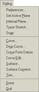
Again, we will go into more detail about these menu items in the upcoming lessons.
LESSON SUMMARY
ISDX is a module in Pro/ENGINEER designed to give the user (whether it is an Industrial Designer or a Product Engineer) the ability to create free-form surfaces from three-dimensional curves, curves projected onto surfaces, or curves sketched on a two-dimensional plane – all without needing a single dimension.
Designers must understand the downstream manufacturing operation and Engineers must understand the surface curvature and aesthetic nature of product design. By working in Pro/ENGINEER with ISDX, both Designers and Engineers can accomplish both goals, and create robust models that adapt to changes much easier than using two separate software packages.