Lesson 12

Lesson Objective: In this lesson, we will learn how to use image files as a basis for creating models using style. Included in this lesson will be how to import images, and how to scale and position images.

TRACE SKETCH PROCESS
In Style, you can use image files as a guideline for creating geometry by tracing key features of the sketch. In general, this really only works if your sketch represents a traditional orthogonal view, such as TOP, FRONT, RIGHT, BACK, BOTTOM or LEFT. Isometric sketches of products do not translate well into 2D, although you are welcome to try.
The sketched image is first imported into Style and placed on one of the datum planes, typically FRONT, TOP or RIGHT.
Then, once the sketch is placed, you can fit the sketch to ensure proper location and scale of the model. To fit the sketch, you identify an origin and specify the scale of the sketch.
IMAGE TYPES
The following types of files can be imported into Style to use as a trace sketch:
· Bitmap (BMP) - *.bmp
· GIF - *.gif
· JPEG - *.jpg
· Portable Network Graphic (PNG) - *.png
· PTC Color Texture - *.tx3
· PTC Decal - *.tx4
· PTC Image File - *.imf
· RGB – *.rgb
· Run-Length Encoded Version A – Rasterfile (RLA) - *.rla
· Shima-Seiki - *.pic
· Targa Graphics Adaptor (TGA) *.tga
· TIFF - *.tif
NOTE: Do not be confused with other file types that can be imported into the part itself and then used to import curves into style, such as IGES, Adobe Illustrator (*.ai), regular datum curves, STEP, etc. Trace sketching is exclusive to the style feature itself.
INSERTING A SKETCH INTO STYLE
To demonstrate the process of bringing a sketch into style, we will create a brand new part file called Brush. Once inside this part, start a new style feature.
Next, go to Styling, Trace Sketch. This will bring up the following window.
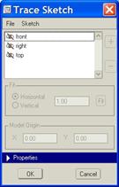
To start, you click on the plane where you want to place the first sketch. In our example, we are going to pick on the front plane in the window. When we do this, the file open dialog box pops up, as shown below.
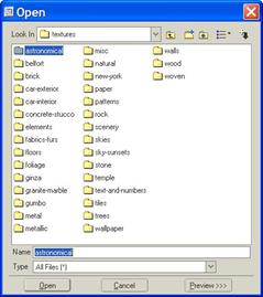
It may default the search location to the Pro/PHOTORENDER texture library, as shown above. If this happens, simply pick on the working directory icon, or switch over to your working directory from the pull-down field.
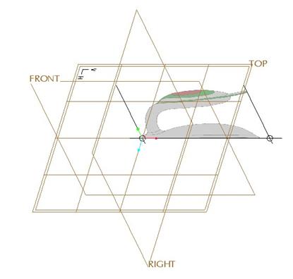
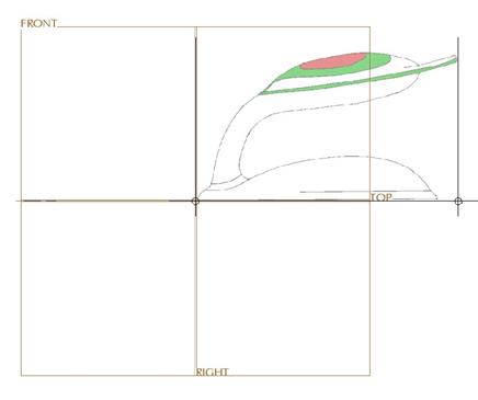
Once in your working directory, select the file entitled Side_View.gif. When we do this, the image appears on the model on the FRONT datum plane, as shown below.
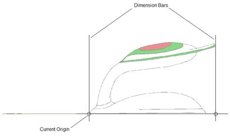
In the Trace Sketch window, we can now see some other fields available, as shown below.
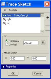
We will go ahead and set or view orientation to a FRONT view, so we are looking straight at the sketch, as shown below.
NOTE: This may be one of the times when working only in a single viewpoint is best, so we can concentrate purely on fitting the sketch.
Looking back at our Trace Sketch window, we can see that there is a blue bar entitled Properties which is currently collapsed. Click on the blue bar to expand out this section, and we will see all of the options available to us at this time, as shown at the top of the next page.
Fitting the Sketch
Now that we have our first sketch on the FRONT datum plane, we need to consider any moving or scaling that has to happen. Right now, we can see that the lower left corner of the sketch is sitting at the origin of X=0 and Y=0. We can also see that the overall width of our sketch is 200.00 inches long.
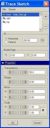
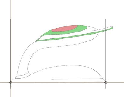
On the model itself, we can see some lines. These lines are called dimensioning bars, as shown in the following figure.
We can also see that the overall length governed by the dimensioning bars is from the far left point on the sketch to the far right point on the sketch (at the end of the handle). Suppose we know the dimension from the left side (where it currently sits) to the right side of the bottom portion. We can drag the right dimensioning bar over to the location that we know, as shown below.
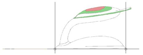
If we know this distance to be 6.0 inches, then we will enter that in the field provided for the horizontal distance, as shown below.
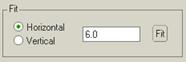
Click on the Fit button, and the entire sketch will scale proportionally. Zoom in on the sketch once it has been resized, and you will be able to see it still looks the same.
Next, we can adjust the origin location of our sketch so it is centered on our datum planes. Turn the datum planes back on, and you can see that the RIGHT datum plane is currently at the left side of the sketch (where the current origin is), as shown below.
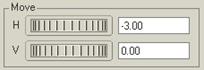
In the section entitled Model Origin, where we have values of X=0 and Y=0, we want to leave this alone. We do want the model origin to be centered on the datum planes. But, we want the sketch centered about the RIGHT datum plane, so we need to translate or move the sketch -3.0 inches, as shown in the following figure.
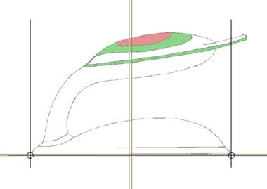
Once we do this, we can see that our sketch is centered exactly as we need it.
There are other options in the Properties section of this window. Transparency is used to set the transparency of the sketch with respect to the model. Its default value is 50% transparent. This is probably a good start, because we want to be able to see our curves as we sketch them. You can adjust this value to your taste.
Rotate is used to rotate the sketch about its origin on the current plane. For example, a value of 45 would give us the following.

For our example, we want to leave it at 0.0. Finally, the Scale dials give you dynamic control over scaling the model. There is a padlock icon that is pressed in at the right of these dials. This is what keeps the sketch’s aspect ratio intact as we resized it. If you needed to be able to scale the horizontal and vertical independently, unselect the padlock first.
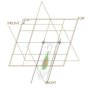
Now that we have our first sketch in, we are going to bring in another. To do this, first go to a default view, and then click on the top plane in the field at the top of our Trace Sketch window.
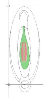
When the File Open window appears, get the Top_View.gif file in our working directory. It will come in initially as shown below.
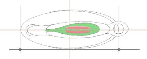
The first thing you will notice is that we can not see the first sketch. This is because the scale of this new sketch is so much larger than the other one. Switch over to a top view, and turn off datum planes. You will also notice that our dimensioning bars are currently going from one side to the other, whereas on the last sketch, we used the front to the back of the bottom piece of our part.
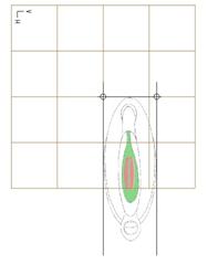
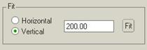
We can easily adjust this by clicking on the Vertical option in the Trace Sketch window, as shown below.
This will bring up the bars in the direction we saw with the first sketch.
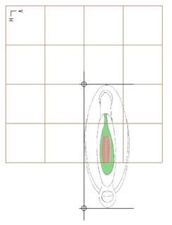
Now, we will drag the bottom bar up until it is at the same location as it was on the first one, as shown below. NOTE: Active plane grid has been turned off for better clarity.
Now, with the dimensioning bars in the same place they were on the first one, we will change the vertical distance to 6.0 and click on the Fit button. Once we do this, go to a default view and zoom in on the model. You will now be able to see both sketches.
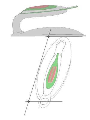
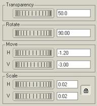
We will need to manipulate its location and orientation to get it completely right. Therefore, we will first use the Move sliders and translate the part vertically by -3.0. This will result in the following.
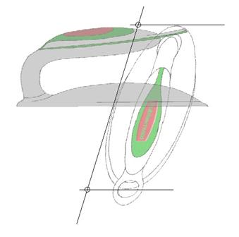
Next, go to the Rotate slider, and change its value to 90.0. The orientation is now correct.
We will now go to the Move sliders again, and change the Horizontal distance to -1.2, which will place our model at the location we want it (as shown from a TOP view).
The values in our Properties section of the Trace Sketch window, look like the following.
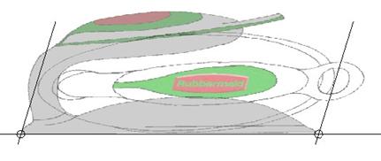
Rotate the model, and you will see how we can easily start to create our style curves and surfaces, as shown at the top of the next page.
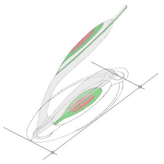
Click on OK from the Trace Sketch window to complete the importing of sketches into our style feature. If we needed to go back and turn off the visibility of one or all of our sketches, we would go back to Styling, Trace Sketch, and then adjust the visibility in the top portion of the window.
To turn off the visibility, click on the eyeball to the left of the datum plane that lists the sketch. This will place a red slash through the eyeball and the sketch will be hidden. To unhide it again, click on the eyeball once more to remove the red slash.
Now, we are able to create our style curves and surfaces. The following figure shows how close we got with our actual size we wanted.
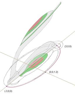
In the previous figure, we created a simple planar curve and controlled the endpoints and midpoint as indicated by the coordinates in the figure. You can see that we are able to use the sketch with confidence.
The next figure shows how we might create some surfaces for this style feature, and how closely they follow our sketches.
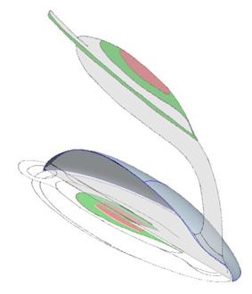
NOTE: The sketches remain visible after you finish out of the style feature. This means that you can use regular datum curves, surfaces, solid features, etc and trace the existing sketches.
Save and close this part.
LESSON SUMMARY
Assuming that you have a nice set of orthogonal sketches (that are reasonably drawn proportionally), you can use these sketches as the basis for creating geometry in Pro/ENGINEER using the style feature.
Bring in the sketch onto a datum plane, scale, rotate and move the sketch to get it exactly where you want it.
Create you style curves and surfaces, or other Pro/ENGINEER geometry using these sketches as a basis.
EXERCISE
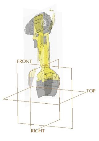
Create a new part called Drill. Using the methods described in this lesson, bring in the Drill_Side_View.jpg and Drill_Front_View.jpg image files as a basis for your style features. The overall height of the drill should be 12 inches, and we want the drill’s base to lie on the TOP datum plane, centered about the FRONT and RIGHT datum planes.
The resulting trace sketches should look like the following.
On Your Own…
If you feel ambitious, try making the yellow part of the drill (top revolved surface, handle, and bottom surface). Use a combination of Style and regular surface features.