Lesson 11

Lesson Objective: In this lesson, we will learn about trimming surfaces, meshing surfaces, displaying entities, style parameters and repeating a style command.
ENTITY DISPLAY
When you are working in Pro/ENGINEER, you have the ability to hide datum and surface items from the model tree. In a single style feature, you also have that ability, but it only remains that way while you are in the style feature.
There are several different commands that can be accessed with the right mouse button that affect the display of entities.
· Hide – Hide the selected entities in the style feature.
· Unhide All / Unhide All Entities – Unhides all previously hidden style entities. Both of these commands do the same thing. The Unhide All option is available under View, Visibility in the menu bar, while the Unhide All Entities is a shortcut with the right mouse button.
· Isolate – Hides all entities in the style feature except the ones selected.
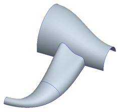
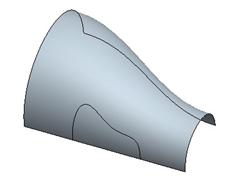
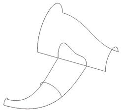
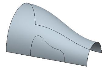
To demonstrate this functionality, open up the Surface_Operation.prt part file. It will initially look like the following.
Edit the definition of the style feature. Once inside the
style superfeature, use the select tool (![]() ) and click on the curving surface
so it highlights, as shown below.
) and click on the curving surface
so it highlights, as shown below.

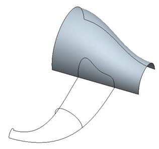
With this surface highlighted, hold down the right mouse button and select Hide. The surface disappears, leaving only the curves visible.
Now, using the Ctrl key, select the four curves that make up the curvy surface. Do not select the one projected onto the top surface. The following figure shows these selected curves.
Right mouse click again, and select Hide one more time. We are now left with the following.
Now, go to View, Visibility, Unhide All from the menu bar. All of the previously hidden curves and surfaces will re-appear on the model.
Now, select the surface that we hid before, as shown below.
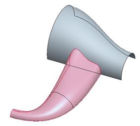
With this surface selected, right mouse click and select Isolate. Every other curve and surface will disappear, leaving only the selected surface, as shown below.
Finally, click anywhere in the working window with the right mouse button and select Unhide All Entities. Every style curve and surface is visible again. Keep this model open for the next topic.
SURFACE MESH
One of the styling preferences is to show a surface mesh of all style surfaces. This is accessed through Styling, Preferences in the menu bar when in the middle of a style feature definition.
In the preferences window, there is a section entitled Surface Mesh, as shown below.
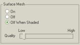
There are three options.
· On – Always on, even when the model is shaded.
· Off – Always off.
· Off When Shaded – The default setting, means that in Wireframe, Hidden Line or No Hidden Line display, the mesh is visible, while in Shaded mode the mesh is not shown.
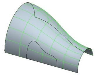
The quality setting affects the density of the isolines for all surfaces simultaneously. The following figures show the three different settings.
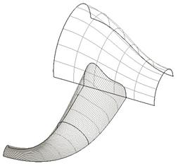
On
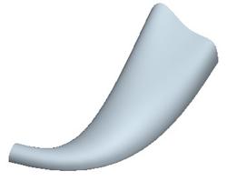
The view on the left could be “On” or “Off When Shaded”. The view on the right is only available with “On”

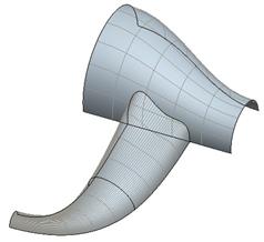
Off
The figure on the left can only be found when the setting is “Off”. The figure on the right can be either “Off” or “Off When Shaded”.
When using quality, you can get a better sense for the quality of the surface. The higher the setting, the more obvious it will be if there are any blemishes in the surface, as we can see at the top of the next page around the bended surface location.
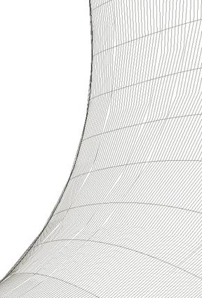
As you can see from the figure above, there are gaps and uneven areas in the surface mesh around this bend.
TRIMMING SURFACES
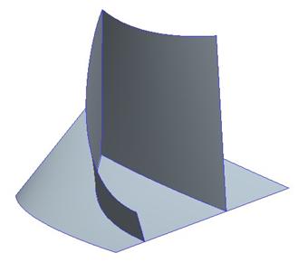
When you are working in style, you may often create COS curves that lay on a surface. As in this example, we have two surfaces that are intersecting each other. We used a COS curve to define the boundary between the two surfaces, but each surface is a complete surface, as we can see below.

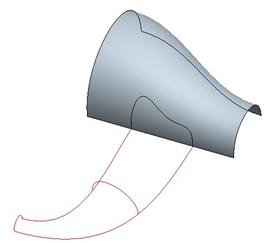
Therefore, we are going to start by hiding the surface and the curves that make up the curvy handle so we are left with the top surface and the trimming curve (boundary COS), as shown below.
To trim the surface, click on the surface trim tool in the style toolbar, as shown below.
![]()
Next, select on the surface to trim. Pick on the surface itself, and then click the middle mouse button to accept it. Now, pick on the curve that will act as the trimming object. Select the COS curve and then click the middle mouse button to accept it.
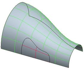
The entire surface (on both sides of the boundary curve) will mesh in green, as shown below.
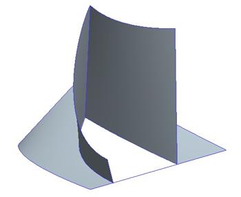
We can keep both sides of the surface by clicking with the middle mouse button. Or, if we want to remove a surface patch, click on that surface to turn the mesh red, as shown for the small surface patch inside the Boundary COS (see figure at the top of the next page).
When you click on the middle mouse button, only the part of the surface that has the green mesh will remain, as shown in the following figure.
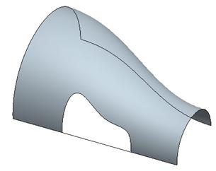
Now, right mouse click and select Unhide All Entities to see the resulting style feature.

NOTE: You could also have reached this same point if you had finished out of the style feature, and then performed a regular surface merge between the two style surfaces (even though they are in the same style feature).
Save this model.
STYLE PARAMETERS
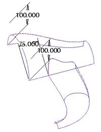
There are several dimensional-type functions in style that we have used. Most of these have been related to the soft point or the tangency line. Working with the same model, select the curve edit tool and select the curve shown below.
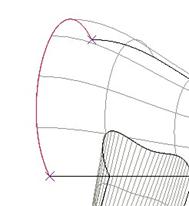
Then pick on one of the endpoints to see the tangency line. Go to the dashboard and open up the tangent slide-up panel. You will see the length parameter shown below.
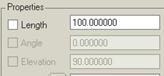
The little check box next to the word Length is used to make this value available for editing outside of the style feature. In other words, it makes it a style parameter. Go ahead and check this box.
Do the same for the length parameter at the other endpoint for this same curve. Then select the COS curve endpoint shown below.
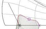
Open up the Point slide-up panel, and you will see the Offset From Plane value shown.
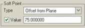
Check it as shown in the previous figure to make this dimension value available outside of the style feature. Then, click on the blue check mark to complete the style feature. In the model tree, right mouse click on the style feature, and select Edit. You will see the three parameters that we checked appear on the style feature, as shown below.
You can now edit these as if they were regular dimensions.
The following are the different parameters that are available to select:
· Tangent Line Length
· Tangent Line Angle
· Tangent Line Elevation
· Offset Plane values for Planar Curves
· Soft Point Location: Parameter, Length Ratio, Offset from Plane and Length
· Internal Datum Parameters (used to create internal active planes), such as offset or angle values.
REPEAT COMMAND
When you want to repeat a command that you just did, such as create planar curve, you can click on the following icon in the system toolbar.
![]()
This will repeat the previously used command.
LESSON SUMMARY
When you work in style superfeatures, often you may find it useful to hide entities. Use the Hide command to blank the viewing of selected objects. Use Isolate to hide all entities except those selected, or unhide all entities that were previously hidden.
When trimming surfaces, select on the surface patches you wish to remove by making them turn red. Any surface with a green mesh will still remain.
Use style parameters to make quick modifications outside of the style feature.
EXERCISE
Open up the part entitled Trim.prt. It will initially look like the following.
Use the trim surface command to get rid of the three-sided surface patch between the two tall surfaces. Try using the hide/isolate/unhide commands to make it easier to work. The final style feature will look like the following.
Save and close the model.