Lesson 8

Lesson Objective: In this lesson, we will delve in deeper to the control of curves, with an in-depth discussion on curve point types, control curves, adding points, splitting curves, and combining curves.
CURVE POINT CATEGORIES
When you create curves in ISDX, you define points and the curve connects these points. There are two main categories for curve points. These are:
· Free – The point is not constrained to any other entities or geometry.
· Constrained – The point is tied to another entity by either a fixed point or a soft point.
Example of Free points:
Create a new part called Control. Once inside the part, create a new style feature. Accept the default active plane as the TOP datum plane, and turn off the visibility of datum planes.
Go to a TOP view, and create the following curve by picking where you see the three points below (approximately). Make sure you use the Free curve option in the dashboard.
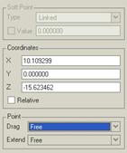
Once you create this curve, go to the curve edit tool and pick on the leftmost point. In the dashboard, click on the Point slide-up panel. It should look similar to the following.
There are several clues that let us know that this point is absolutely free. The first is that the points themselves are small filled-in dots. The second is that the Soft Point area of the Point panel is grayed out. You will see this similar result for any of the points on this curve.
Now, click on the Planar option in the dashboard. In the message window, click on Yes to accept this change. The curve and its points do no look any different, but click on one of the endpoints again, and look at the Point slide-up panel.
The biggest difference in this case is how the soft point type is now showing “Linked”, as we can see below. This, in itself, is not a complete indicator that the point is not completely free, as we will see in a second.
Again, any of the points on this curve will look similar to this one. One of the things you will notice is that the soft point type is still listed as “Linked” as if it remembered its last state.
Dragging Free Points:
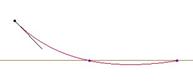
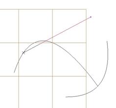
While this curve is still active, go to a FRONT view, and you will see the three points, as shown below. Select on the Free option in the dashboard to convert this curve back to a free curve.
![]()
Click on the leftmost point to activate it. In the Point slide-up panel, click on the down arrow to see the options under the Drag field, as shown below.
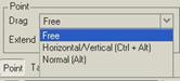
If you wanted to freely move around the point, you would leave the drag option as Free. Hold down the left mouse button over this point and move it up and to the left, as shown below.
Now, notice there are two other options. The second one (Horizontal/Vertical) lets you move only in the horizontal or vertical direction with respect to the current active plane (even if it is not a planar curve). We will come back to demonstrate this in a moment.
The last option (Normal) would allow you to move the point perpendicular to the current active plane. If you want to use the keyboard in conjunction with the mouse, you only need to hold down the Alt key (indicated in parenthesis in this drop-down list) and use the left mouse button.
We will try that now with the second point. Hold down the Alt key on the keyboard and then hold down the left mouse button over the second point and drag the point in any direction (either up or down) and you will see that it is forced to move only straight up or straight down. Move it to the location shown below.
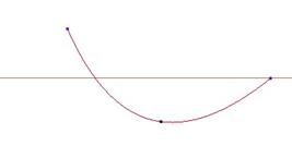
To demonstrate the Horizontal/Vertical drag motion, go back to a default view. Click on the third point to activate it, and then hold down the Ctrl and Alt keys together and drag the point with the left mouse button. You will notice that it will only move either in the vertical direction (as defined on the active plane) or the horizontal direction (as defined on the active plane). Once you let go of the mouse, you can then re-click on the point and drag it in the other direction. Use two different clicks (one for vertical and one for horizontal) to get it to the location shown below.
Click with the middle mouse button to finish this curve edit.
Soft Points
We are now going to look at the soft point and how to control it in more detail. Soft points, if you will recall from Lesson 4, are denoted by an open circle at the point location. A soft point is free to move along the curve on which it is constrained. It does not have to be an endpoint, either.
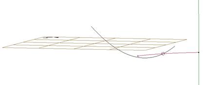
To demonstrate this, go to a TOP view again, and create a new curve. Use the Free option, and select the three points starting from the lower left. When you create the middle point, hold down the SHIFT key on the keyboard to get it to snap to the first curve that we created, thus creating the soft point. After you click the third point, stop for a moment. Do not press any mouse buttons or keyboard keys. The curve will look like the following from the TOP view.
Now, rotate the model, and you will see a green line sticking through the last point that we defined. This green line is perpendicular to the active plane, and represents the depth away from the plane.
When you are using the free option, any free points that you define are projected onto the active plane (even though they don’t need to remain there). As soon as we defined the middle point by constraining it to the first curve, all the free points shifted down to be at the same depth value (almost as if we had offset an active plane by the amount needed to locate our soft point).
When we rotate the model, we can see the green line on the active point. Until we click outside that green line to specify another point, we are still defining the depth of our point away from the active plane (although not in explicit dimension values).
Click on the green line in the location indicated below at this time, and you will notice that our third point shifts down to this location (second figure below).

gives you…
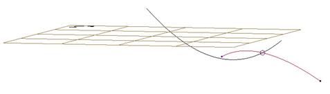
From a TOP view, it still looks the same, because we shifted the depth straight down. This is another reason why working in four viewpoints may be valuable to you.
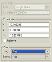
Now, we are going to drag our soft point. Click on the edit curve icon and then click on the soft point that intersects the first curve. In the Point slide-up panel, we see the following.
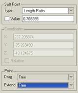
Unlike a “Free” point, we can not directly control the X, Y, and Z locations for soft points. They are grayed out, but they will show us the current value for our reference. We can control the location of the soft point with the field at the top.
Currently, the value of our point is approximately located 77% along the length of our first curve. If we were to change this value to 0.5, we would locate the soft point at the center of our first curve. The following shows the result of doing this.

If we change the value to 1.0, we locate it at the end of our curve, as shown below.
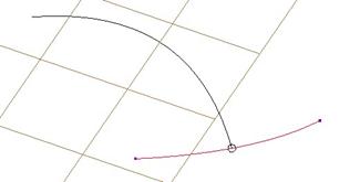
We would have gotten this same result if we had dragged the point using the left mouse button until it stopped at the end of the curve.
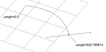
Next, we are going to change the soft point type to Length using the pull-down. We can see that (at the end of our curve), the length value is 502.795914, as shown below.
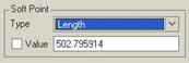
We could specify an exact value for this point based on the actual length of the line. The following figure shows the values at the endpoints of this line.
If we change the value to 300.0, we get the following.
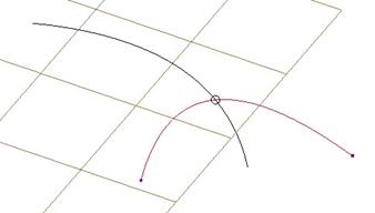
Next, we will change the soft point type to Offset from Plane. When we do this, turn on the display of datum planes, and select the RIGHT datum plane. The current offset value from this plane is shown below.
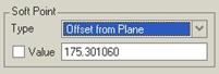
We can change this value to 250.0, and our point will be at the following location.
The distance that we enter in this field is measured from the point normal to the plane in a straight line. If we want to make this point a “free” point, all we would have to do is select the Unlink option, or hold down the shift key and drag the point away from the first curve so it no longer snaps to it.
We will leave it alone for now at the last value of 250.0 offset from the RIGHT datum plane.
Fixed Points
The second type of constrained point is a fixed point. This point is not only constrained to another entity, but it is not permitted to move away from its point. It is represented by an “x” on the point.
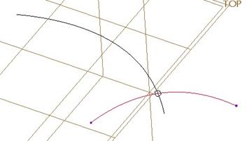
To see this, we will continue with our current curve edit. In the Soft Point type field, change the value to Lock to Point. It will snap to the closest point on the curve, which in this case is the endpoint, as shown below.
We can clearly see the “x” where this point touches the end point. If we were to try to drag this using just the left mouse button, we would not be able to.
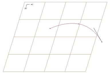
Click on the middle mouse button to complete this second curve. Then go to a TOP view, and start a new curve. Change the type to Planar, and click on the two points shown below, starting with the one at the upper right.

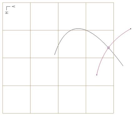
Now, click on the edit curve option and drag the point (using the SHIFT key) closest to the curve. Move the point towards the left side of the first curve. You will notice that it snaps to the endpoint where our other two curves intersect. Now, drag it over towards the other end of the first curve, and you will see it snap to another location, as shown at the top of the next page.
Because we are using the Planar option for this curve, there are only two exact locations where the first curve intersects the active plane, and we can only tie the end of our curve to one of these two locations.
Since the locations are fixed, our points become fixed, as we saw in the figure above with the “x” symbol.
You will also see fixed points if you tie to vertices on geometry and not to a specific edge. Click on the middle mouse button to finish this curve. Next, hold down the Ctrl key and select all three curves, and delete them.
CONTROL POINTS
When you create curves, you have the ability to manipulate the points on the curves themselves, or you can use control points. Control points give you the ability to refine the shape of the curve, especially if you don’t have many internal points.
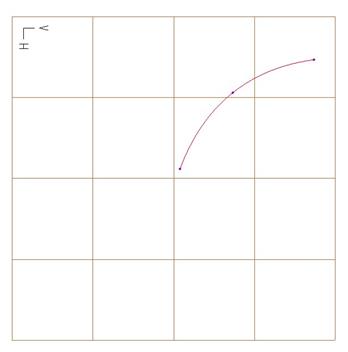
To demonstrate this, create a new curve using the planar option. Our active plane should still be the TOP datum plane. Sketch the following curve, from left to right, at the point locations shown.
Down in the dashboard, you will see an option for Control Points. Select this option, and you will see the following on your curve.
We can see that our two internal points have disappeared, and now we can see multiple control points connected by purple lines. If we were to click out on the active plane to place another point, we are actually defining a control point location, as shown below.
We can see that the shape is very different than what we would get if we were not using control points. To demonstrate this, click on the Undo icon in the system toolbar, and then turn off the Control Points option, and click in the same location to place another point. The difference is shown below.
Turn on control points again, and you will see the following.
Click on the edit curve tool, and drag out the control point in the middle of the right side, as shown below.
Finish out of this curve, and then click on the blue check mark to complete the style feature. Close this part without saving it.
Other Important Information:
You can control the X, Y, and Z location of control points, but only the first and last control points on a curve can be soft points (i.e. the endpoints of the curve). Outside of control point mode, you can specify any internal curve point to be a soft point.
ADDING POINTS
One of the things we talked about in Lesson 4 was that the more points you have in a curve, the more bumps or dips you will have. It is always best to work with fewer points. Sometimes, however, you may need to add points to either get better control of your curve shape, or to eventually split up the curve (as we will see in the next topic).
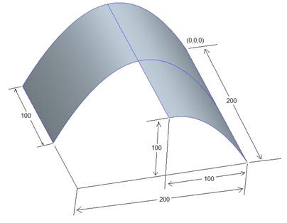
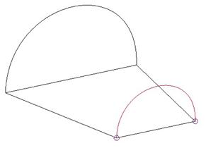
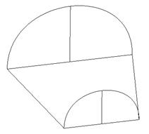
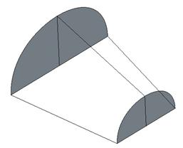
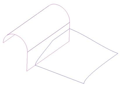
To demonstrate this, open up the part entitled Curve_Points.prt. It will initially look like the figure at the top of the next page.
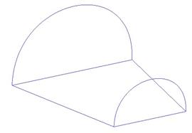
Suppose we want to make four surfaces in the existing style feature. We could easily make the bottom, flat surface, because we have four boundary curves we could pick. The same is true for the cylindrical surface at the top, since we have four boundary curves for this one as well.
The problem would be if we wanted to make the two end surfaces. Each of these consists of only two boundary curves – one straight line and one semi-circle. Since we can only create three or four-sided surfaces, we can not make one from these two without dividing it up into more segments.
Therefore, the first thing we need to do is add an additional point to each of the semi-circles. To do this, we first need to edit the definition of the existing style feature. Once inside the style superfeature, click on the edit curve tool and select the smaller semi-circle, as shown below.
To add a point, simply hold the right mouse button down over the highlighted curve. You will see the following options.
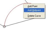
To add a point at the exact location of the mouse, select the Add Point option. To add a point to the exact center of the curve (equivalent to Length Ratio = 0.5), then use the Add Midpoint option.
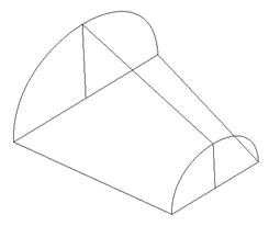
We will use the Add Midpoint option, and we will see the following.
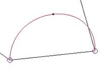
Repeat this process for the larger semi-circular curve, as shown below.
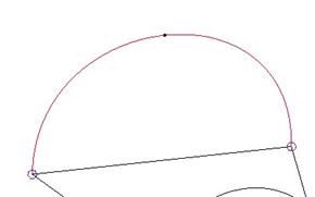
Click on the middle mouse button to finish this curve edit, but do not leave the style feature. We are going to continue working with this style feature in the next topic.
SPLITTING CURVES
Now that we have a midpoint defined for each of our semi-circular curves, we need to split these curves up into two individual curves. To do this, first edit the smaller semi-circular curve to see the midpoint again.
Hold the right mouse button down over the midpoint and you will see some options, as shown below.
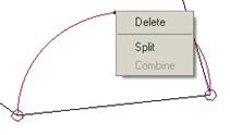
We will select the Split option, and then only one half of the semi-circular curve will be highlighted, indicating that the split was successful, as shown at the top of the next page.
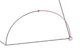
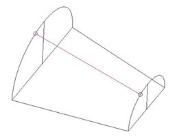
Repeat this same split for the larger semi-circular curve. Next, we are going to create a curve using the Free option. We are going to hold down the Shift key and select the two locations shown below.
Next, switch over to the curve edit tool, and drag the top soft point until it stops at the point that we used to split the curve (which is now an endpoint), as shown below.

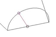
For the bottom soft point, click on it and go to the Point slide-up panel. Change the value for Length Ratio to 0.5, which will snap it to the center of the line, as shown below.
Repeat this process to create a line connecting the back line with the large semi-circular curve. The result will be shown below.
Since we split up the two semi-circular curves, we are no longer able to create the cylindrical surface at the top, because we actually have six boundary curves instead of four. Therefore, we should create another curve that connects the two midpoints of the semi-circular curves.
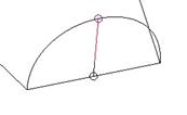
Start by creating a new curve using the Free option, and pick on the two semi-circular curves using the shift key, as shown below.
Then, edit this curve and drag the two soft points until they stop at the midpoints of the semi-circular curves, as shown below.
Now we can begin to make surfaces. Click on the surface tool and start by picking the three boundary curves that make up one of the small quart circular surfaces, as shown below.
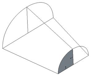
Repeat this process to create the other three quarter circular surfaces, as we can see in the following figure.
Now, use the last curve that we created as one of the boundary curves to create half of the cylindrical surfaces, as shown below.
Repeat this process to create the other half of the cylindrical surface.
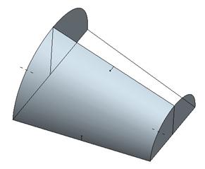
Lastly, use the four straight curves at the bottom to make the flat surface. Then, click on the blue check mark to complete the style feature, and our final model looks like the following.
Save and close this model.
COMBINING CURVES
Just as there are times when you may need to split a curve up into multiple curves, you may also need to combine two or more curves into a single curve.
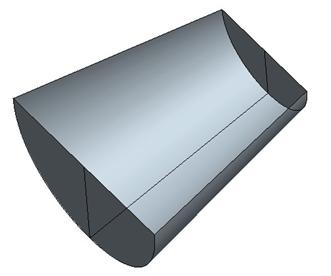
To demonstrate this, open up the model Curve_Combine.prt. It will look like the following.
On the flat portion of the extruded surface, we can see two style curves. Originally, this was the design that we wanted. After some consideration, however, it was determined to make it one smooth curve instead of two non-tangent edges.
If we edit the definition of this style feature, and then click on the curve edit tool, we can select each of these independently, as shown in the following figure for one of the two style curves.

We could delete these two curves and then sketch a new one, but we might have style entities that would fail internal regeneration. Therefore, we will combine these two separate style curves into a single style curve.
Therefore, we will do the reverse of the split command. With one of the two curves selected for editing, we will hold the right mouse button down at the endpoint between the two curves. We will get the following options.
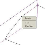
We will select Combine from this list, and the curve will update to make a smooth transition between the two previous curves, as we can see at the top of the next page.
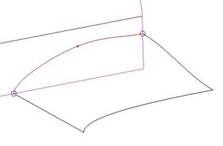
We can now drag the point as if it were any other internal point, or we can even delete it to eliminate any dips or bumps in our curve.
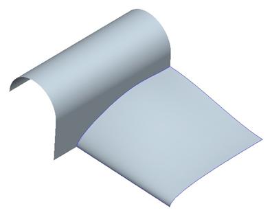
We can also create a single surface now using the four boundary curves, where before we would have had to add an additional curve to break up the surface into two, since we had five boundary curves.
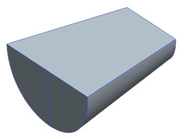
The resulting model with the surface added to the style feature is shown below.
Save and close this model.
Restrictions for Combining Curves:
There are two main restrictions for combining curves. The first is that you can only combine two curves of the same type. For example, you can combine two free curves, or two planar curves, or two COS curves, but not a free and a planar, or a free and a COS, or a COS and a planar.
The second restriction is that two COS curves must be on the same surface to combine. You can not combine a COS curve with another one if it is on a different surface, even if that surface connects and is tangent to the first one.
EXTENDING CURVES
The last topic for this lesson will be to learn how to extend curves. When you initially create a curve, you can keep picking points to lengthen the curve. Once you accept the curve, you can not directly click on a new point to add it outside of the curve.
You can add internal points directly using the middle mouse button, but to add additional points to lengthen the curve, you must use the extend functionality.
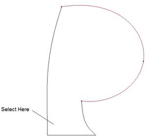
To demonstrate this concept, open up the model entitled Curve_Extend.prt. It will initially look like the figure below.

For this example, we want to add an additional point onto the large somewhat circular curve. Therefore, we will start by editing the definition of the style feature, and then select on the curve edit tool and pick on this curve.
Next, open up the Point slide-up panel. At the bottom, there is a pull-down used to define how we extend curves. There are three options, shown below.
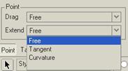
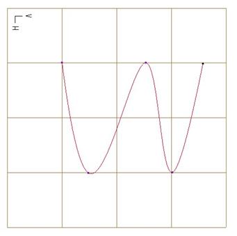
To demonstrate how these work, we will always select the point shown on the figure at the top of the next page.
Free Extend
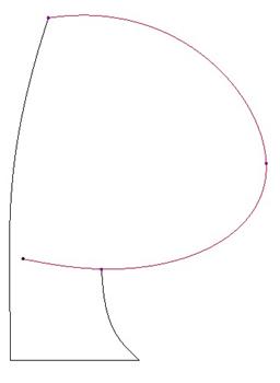
We will start with the default option of Free. If we were to drag the last point on this curve, the entire curve would adjust, but the total number of points (3 in this case) would not change.
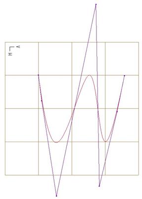
To add a point while extending, we will hold down the Shift and Alt keys at the same time, and then either click the location for the point or drag the curve. We will click on the location shown in the above figure. This will result in the following.

We can see that the original curve had to drastically change shape to maintain the internal tangency of the curve.
Now, click on the undo button so we can try a different extend type.
Tangent Extend
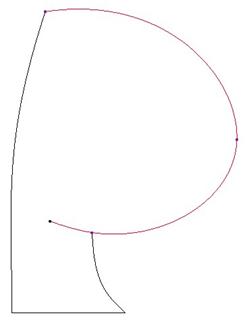
In the Point slide-up panel, change the extend type to Tangent, hold down the Shift and Alt keys again, and pick in the same location as before. This time, we will get the following.
The original curve had to change a little to update the smoothness, but it still maintains the overall shape it had. We can see that the new end point is not where we picked. This will be explained shortly.
For now, go ahead and undo this change to try the last extend type.
Curvature Extend
In the Point slide-up panel, change the extend type to Curvature, hold down the Shift and Alt keys one more time, and pick in the same location as before. The result of this is shown at the top of the next page.
This looks similar to the tangent condition, but the distance out to the left that this went is a lot shorter, and it too did not go where we picked. This will be explained in the next section.
What is going on?
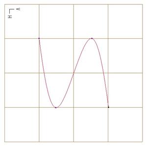
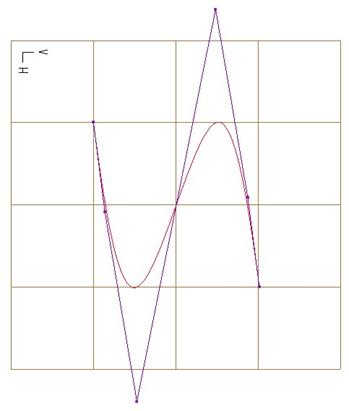
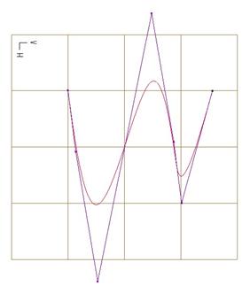
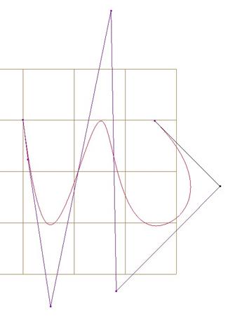
The following figure will be used to explain how it placed the end of our curve for the three options.
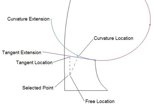
When we used the Free option, the location where it put the new end of our curve is at the exact spot that we picked for the point.
For the Tangent option, it takes the point where you pick, and brings it up to intersect with a line tangent to the curve at the existing end point (“Tangent Extension” in the previous figure). Where these intersect is the location for the new end point (indicated by “Tangent Location” in the previous figure).
For the Curvature option, we first extend out the curve following its original curvature, as indicated by “Curvature Extension” in the previous figure. Next, we take the location where we pick, and we draw a line through this point normal to our curvature extension. At the intersection of this line and extension, we get our new end point, as indicated by “Curvature Location” in the previous figure.
We can now repeat this process to add as many points as we need.
LESSON SUMMARY
Free points can be moved anywhere on the model. Once you tie it to existing style entities or model geometry, you constrain it. Constrained points can either be soft, which are still allowed to move along the entity it is constrained to, or fixed, which are not able to move at all.
You can add/delete points on a curve, or use control curves to better define your shape. Sometimes you may need to split a curve into multiple curves or combine two separate curves into a single curve.
Use an extend (Shift + Alt) to add additional points to the end of an existing curve.
EXERCISE
Create the following style superfeature in a new part called Lesson8.