Lesson 7

Lesson Objective: In this lesson, we will learn how to create curves projected onto surfaces, and talk about using 4 viewpoints.
FREE, PLANAR, COS
Up to now, we have been creating curves based on the Free or Planar conditions. When you click on the create curve tool in the style feature, you have three options for how the curve will be created, as shown below.
![]()
Free implies that the curve lies in true 3D space. You can specify the exact locations of endpoints and internal points, but the curve might not lie in the same plane between these points, even if the points are in the same plane.
Planar implies that the entire curve lies on a 2D plane. You can move the endpoints and internal points around that plane, but the entire curve is completely on that plane.
COS stands for “Curve on Surface” and is used to sketch a curve directly onto a surface, regardless of whether that surface is 2D or 3D.
NOTE: You can convert Free curves to Planar and vice-versa, and you can convert a COS curve to a Free curve or a Planar curve, but you can not convert to a COS curve from a Free or Planar curve using these options.
4 VIEWPOINTS
When working with COS curves, it is often a good idea to use the four viewpoints. To activate the four viewpoints, click on the following icon in the system toolbar.
![]()
This will turn the screen into four different orientations. If you have four orientations already open, clicking on this will return it back to a single viewpoint. As shown in Lesson 2, the four viewpoints are:
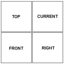
Clicking on any one of the views activates it, and you can use the spin, pan and zoom operations independently for the view selected. If you change the orientation of any of these and want to return to the default orientations, simply click on the default view icon while the 4 viewpoints are open, and they will return to the above configuration.
The Current orientation is whatever you were in when activating the 4 viewpoints. The advantage of working in the 4 Viewpoint mode is that any movement you make in a TOP, FRONT or RIGHT viewpoint will be locked to that 2D space.
For example, if I have a flat, free curve lying on the TOP plane, and I want to move the endpoint away from the TOP plane without accidentally translating it from right to left, then I would make the vertical drag operation in the RIGHT viewpoint.
COS
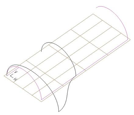
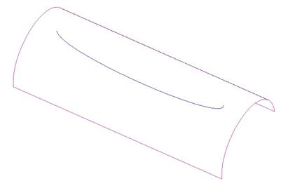
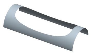
To demonstrate the ability to sketch directly onto a surface, we will open up the part entitled COS1.prt. It will look like the following part.
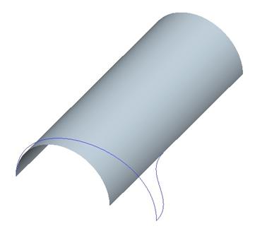
This model currently consists of an extruded surface and a style feature that contains two planar curves. The large arc-shaped curve is normal to the TOP datum plane on both endpoints, while the other curve is normal to the RIGHT datum plane on one side and tangent to the surface edge on the other.
We will start by editing the definition of the existing style feature to create a superfeature containing the existing style entities and the new ones that we are about to create.
Next, we will click on the create curve tool (![]() ). In the dashboard,
change the option to COS, go to a no hidden view, and then turn on the 4
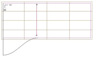
viewpoints so our screen looks like the figure at the top of the next page.
). In the dashboard,
change the option to COS, go to a no hidden view, and then turn on the 4
viewpoints so our screen looks like the figure at the top of the next page.
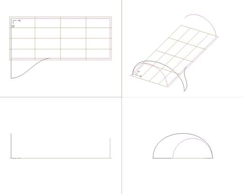
We are going to sketch in the upper left viewpoint. Click within the boundary of the extruded surface in two locations to form a vertical line (do not worry if your line is not perfectly vertical, we will be adjusting this later).
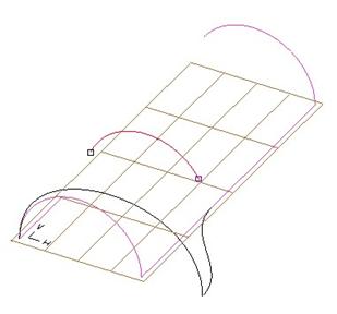
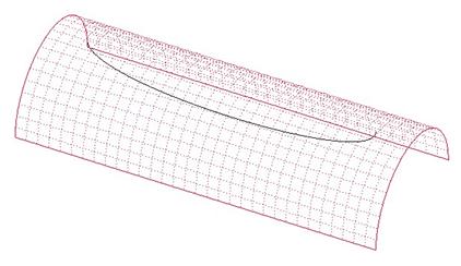
If you look at the upper right viewpoint, you can see that our curve lies on the cylindrical extruded surface, as shown on the next page.
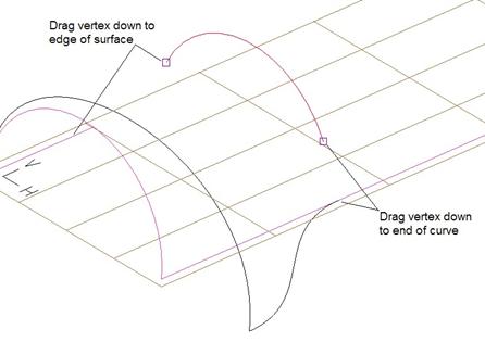
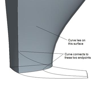
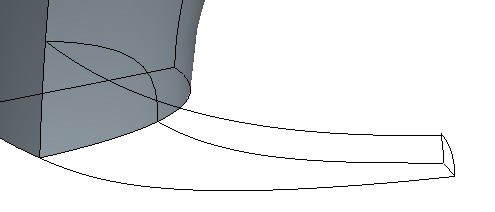
To finish off this curve, go to the curve edit tool, and drag the first endpoint down to the intersection of the surface edge and style curve end using the shift key. Then, using the shift key, drag the other end down to the edge of the surface, as shown below.
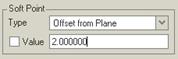
Once both ends have snapped to their respective entities, click on the endpoint that does not touch a style curve, and go to the Points panel to change the location of the soft point. In the Soft Point Type field, change the locating type to Offset from Plane, and then select the RIGHT datum plane.
Give the value for the offset as 2.0, as shown below.
Click on the middle mouse button to complete this curve, which looks like the following.
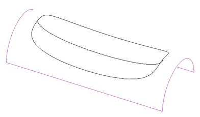
Now create a surface and select the three style curves and the one edge of the surface, as shown below.
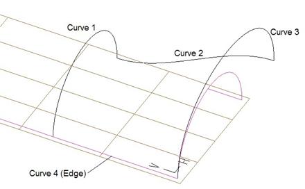
The resulting surface is shown at the top of the next page (with the arrow length value set at 0.5 in the dashboard to make it easier to see the arrows of influence).
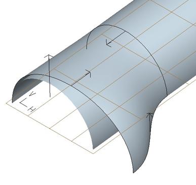
We can see that the cylindrical surface imposes its tangency onto the new style curve at the boundary formed by our COS curve. Finish out of the style feature, and merge these two surfaces together, and you will get the end result.
Save and close this model.
PROJECT CURVE
We just demonstrated how to sketch a style curve directly onto a non-planar surface using four viewpoints to make it easier to see what we are doing.
Now, we are going to learn how to create a style curve and project it onto a surface. To demonstrate this, open up the part entitled COS2.prt. It will look like the following.
Begin by editing the definition for the style feature. Then, click on the following icon to get into projected curve mode.
![]()
You will be prompted to select the surface(s) to project onto. Select the cylindrical surface, as shown below.
Once the surface is selected, click on the middle mouse button to accept it. Now, we are prompted to select the curve to project. Pick on the style curve that lies at the center of the cylinder, and then click on the middle mouse button once it is selected.
Finally, we are prompted to select the datum plane or planar surface that drives the normal direction for the projection. Temporarily turn on your datum planes and select the FRONT datum plane. The curve will project as if it were extruded through the surface normal to the plane.
Therefore, it intersects both sides of the cylindrical surface, as shown below.
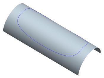
Click on the middle mouse button to finish this projected curve on surface, and then click on the blue check mark to complete the style feature.
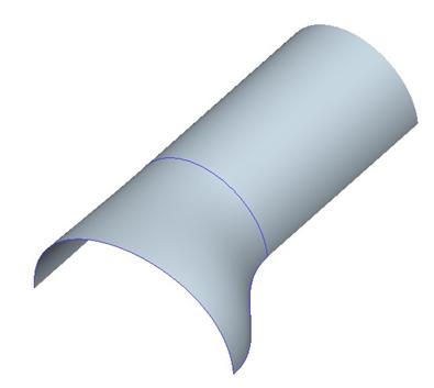
The model will now look like the following.
Now we can use a surface trim tool to cut out the middle of the cylindrical surface using this curve. Be sure to get all of the curve edges when selecting the trimming object. The result is shown at the top of the next page.
LESSON SUMMARY
To ensure that you are going to connect your style surface to another surface, you will want to make sure any boundary curves that touch the surface are either drawn directly on the surface using the COS option, or projected onto the surface using the project curve tool.
Take advantage of 4 viewpoint sketching to make it easier to see what you are doing.
EXERCISE
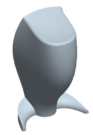
Open up the Speaker.prt part file. It should initially look like the following. We are going to complete the support arm for this speaker, which is already started.
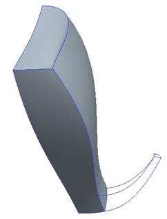
We are going to edit the definition of the existing style superfeature to add a COS curve, as outlined on the next page.
The final curve for this style feature will look like the following.
Then, create a new style feature, and create the four surfaces that make up the support arm. Once all four surfaces are created, finish out of the style feature. Merge the two style quilts together, and then resume the rest of the suppressed features. NOTE: You may have to redefine the Mirror and the Protrusion features because the overall quilt for the model has changed.
The final part in its solid form looks like the figure at the top of the next page.
Save and close the model once you are done.