Lesson 5

Lesson Objective: In this lesson, we will learn how to create basic 3 and 4 sided surfaces, and learn about surface connections and curvature.
FOUR-SIDED SURFACES
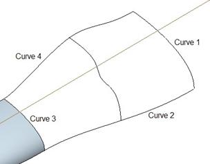
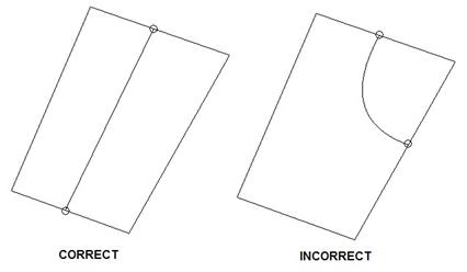
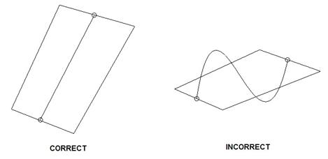
Whenever possible, you should create surfaces using four boundary curves that are not tangent to each other. The following figures show what we mean.
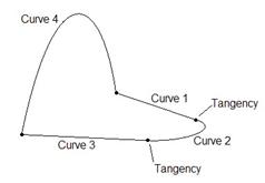

INVALID VALID
The first surface above is invalid, even though there are four boundary curves. The reason is because Curve 1 is tangent to Curve 2, which is tangent to curve 3. In effect, we have created only two boundary curves.
In the second figure, Curve 2 is no longer tangent to Curve 1 and Curve 3, and therefore we have four unique and non-tangent boundary curves.
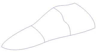
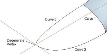
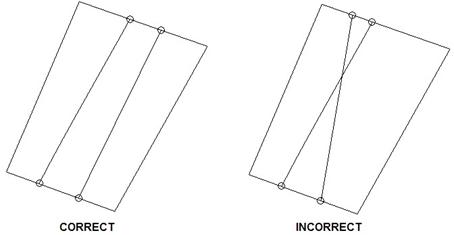
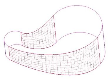
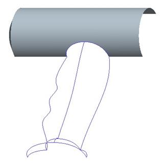
Four-sided surfaces are more robust than three-sided surfaces, but it is not always possible to break up a three-sided surface into multiple four-sided boundaries, as shown below.

It is nearly impossible to define the correct profile of the three internal curves shown above, right.
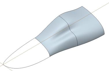
To demonstrate how to create a four sided surface, open up the part entitled Surface_Basics.prt. It will look like the figure at the top of the next page.
In the model tree, right mouse click on the style feature, and select Edit Definition. This will bring us back into the definition of this original style feature.
Next, click on the create surface tool (![]() ). Using the Ctrl
key to select multiple curves, pick on the curves shown in the figure below.
). Using the Ctrl
key to select multiple curves, pick on the curves shown in the figure below.
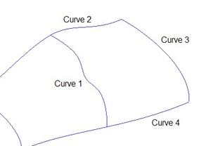
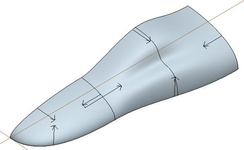
Do not worry that Curve 2 and Curve 4 actually extend beyond Curve 1. Once you finish selecting all four curves, a surface will appear with arrows. You may have to zoom out to see the arrows in their entirety, as we can see below.
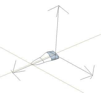
Down in the dashboard, there is a field called “Icon Length” that can be used to change the size of these arrows. By default, it will probably be 10.0, as shown below.
![]()
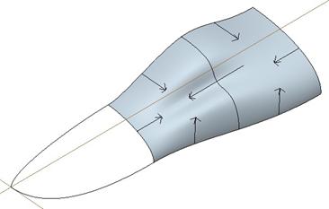
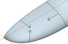
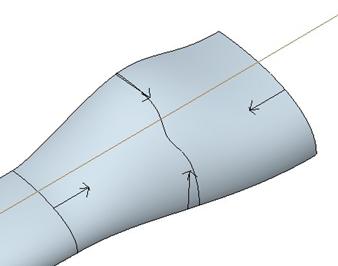
Change this value to 0.5, and then zoom in to see the arrows more clearly. The arrows indicate the influence on tangency/curvature for the surface, as we can see below.
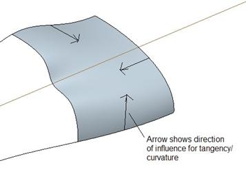
Curve 2, 3 and 4 are all planar curves, therefore, the planes that were used to create these curves are imposing a normal condition on the surface. In other words, all along the three sides, the surface will be normal to the planes used to create the curves.
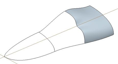
This is what we want, especially if one or more of these planes is going to be used to mirror the part later. Click on the middle mouse button once to finish this first surface. The result is shown below.
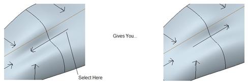
Now, click on the create surface tool again, and pick the curves shown at the top of the next page in the order shown on the figure.

NOTE: You actually do not need to pick the curves in any order for a four sided boundary, but we are doing it for consistency.
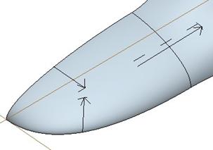
Once you finish picking the four curves, you will see the initial preview of the surface with the arrows, as shown below.
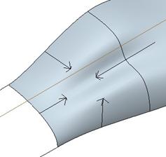
We can see four arrows. The arrows coming from Curve 2, 3, and 4 follow the same rules that we described before. The one that crosses over Curve 1 shows that the first surface that we created is driving the tangency for the second surface.
We will accept this for now, and click on the middle mouse button to finish this surface, which will look like the figure below.
Click on the blue check mark (or click with the middle mouse button again) to finish out of the style feature completely. Then, save the model.
SURFACE CONNECTIONS
When you connect two surfaces in Style, you can define how those surfaces react to each other. As we saw in the previous section, arrows will appear on the surface(s) indicating the direction of influence. There are three possible arrow types that might appear, as outlined below.
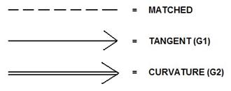
Matched – (G0) – Means that the surfaces share a common boundary, but there is no shared tangency or curvature across that boundary.
Tangent – (G1) – Means that the surfaces share a common boundary, and that at every point along that boundary, the two surfaces are tangent to each other, but don’t necessarily have the same curvature.
Curvature – (G2) – Means that the surfaces share a common boundary, and that at every point along that boundary, the two surfaces are tangent to each other, and share the same curvature.
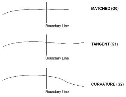
A G2 curvature gives you the best connection between surfaces, while the G0 condition can introduce seam lines and very obvious blemishes. The following figure illustrates this concept a little more clearly.
We will now demonstrate this using the same model that we
were just working on. Start by right mouse clicking on the style feature and
select Edit Definition. Once inside the style feature again, we will
click on the connect surfaces icon (![]() ) and then hold down the Ctrl
key to select the two surfaces that we just created. Once both are selected,
click on the middle mouse button to accept the selection of these surfaces, we
will see the arrows appear on the surfaces once more, as shown below.
) and then hold down the Ctrl
key to select the two surfaces that we just created. Once both are selected,
click on the middle mouse button to accept the selection of these surfaces, we
will see the arrows appear on the surfaces once more, as shown below.
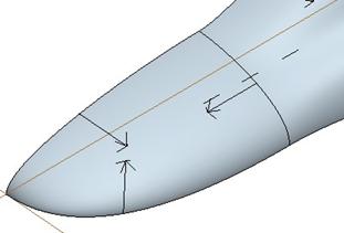
If you click once on the right end of the arrow that crosses over the surface boundary between the two surfaces, it will flip the arrow direction towards the right, as shown below.
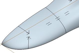
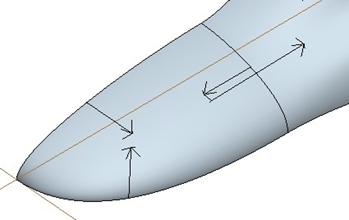
Click once on the center of the arrow (near the boundary curve), and it will change the connection condition from tangent to curvature, as we can see at below.
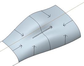
Note the double arrow line indicating the “curvature” condition. Next, hold down the Shift key on the keyboard, and pick on the center of the arrow again. This will remove any tangent or curvature conditions and set it to a “matched” condition, as shown below.
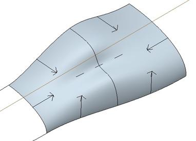
Note the dashed line with no arrows which indicates the “matched” condition. Click once more on the middle of the line to set it back to a “tangent” condition, and then click on the middle mouse button to finish this connection.
Click on the blue check mark to finish out of the style feature completely. Save the model.
THREE-SIDED SURFACES
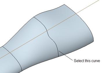
Creating three-sided surfaces in Style is done in pretty much the same way as creating four-sided surfaces. The difference is that two of the three surface boundaries will converge into a single point called the degenerate vertex.
The very first curve that you select will be opposite the degenerate vertex that is created. In our example, we want to select the edge that shares a boundary with another style surface first.
In the same model that we have been working with, right
mouse click on the style feature in the model tree and select Edit
Definition. Click on the create surface tool (![]() ) and then select the three
remaining style curves in the following order.
) and then select the three
remaining style curves in the following order.
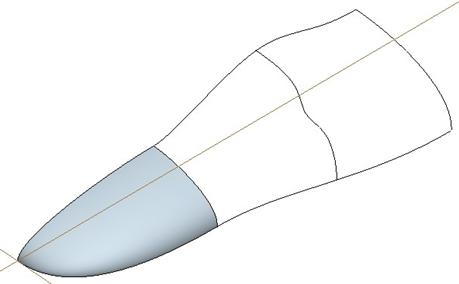
Once all three curves are selected, click on the middle mouse button and the surface will be created, as shown below.
Click on the middle mouse button again to finish this
surface creation. Next, click on the connect surfaces icon (![]() ) again, and select the
middle surface and the one that we just created. Be sure to use the Ctrl
key to pick both surfaces. Click on the middle mouse button once both surfaces
are selected, and the connection arrows will appear, as shown in the following
figure.
) again, and select the
middle surface and the one that we just created. Be sure to use the Ctrl
key to pick both surfaces. Click on the middle mouse button once both surfaces
are selected, and the connection arrows will appear, as shown in the following
figure.
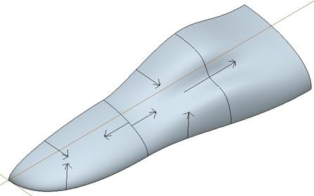
We can see a difference immediately in the assumed connections between these surfaces. Neither one is currently driving the other. Both are assuming a normal condition from the datum plane that lies through the boundary curve (DTM1). If we try and click on either curve’s midpoint or endpoints we don’t see any change.
If, however, we hold the shift key down, and click on the arrow pointing towards the right, we can remove the current condition and create a “matched” condition, as shown at the top of the next page.
Hold the shift key again, and pick on the other arrow pointing towards the left to create a second “matched” condition, as shown below.
Now, click on the center of the bottom-most dashed line (the one closest to the front edge of the model) where it intersects the boundary curve. Both surfaces should highlight in rose, and the message window will prompt:
“Make connection between highlighted surfaces?”
Click on Yes, and you will see the following.
You will find that we can change the direction of influence for this connection, but we will leave it the way it currently is going. Next click once on the dashed connection line and it will go back to a single arrow, as shown below.
What we are seeing is the following. The triangular (three-sided) surface gets is influence from DTM1 at the boundary line. Then, the center surface is influenced in a tangent manner from the triangular surface.
We are unable to change the tangent condition to a curvature condition for this surface connection. Any attempt to change it sets one of the conditions back to a “matched” condition.
If our arrows look like the ones above, click on the middle mouse button to finish the connection, and then click on the blue check mark to complete the style feature. Save the model, which now looks like the following.
INTERNAL SURFACE CURVES
One of the main reasons we are able to toggle between the many different connection conditions for the two four-sided surfaces is because they both share the same front and back curve.
The boundary curve separating the two individual surfaces is actually snapped to the internal portion of the two outside curves.
We are going to demonstrate how to use internal curves by going back to the same model, and edit the definition of the style feature. Once inside the style feature definition, click on the two four-sided surfaces (using the Ctrl key to grab both of them), and then press your Delete key on your keyboard.
In the message window, you will be prompted to delete the selected entities. Click on Yes. You will be left with the following once you delete these surfaces.
Now, we are going to click on the create surface tool again, and select the four curves shown below.
Initially, the surface will only use the four curves and ignore the profile created by the internal boundary curve, as we can see below.
In the dashboard, we can see a field for defining internal curves, as we can see in the following figure.
![]()
Click on the black arrow, and then select the internal curve shown below.
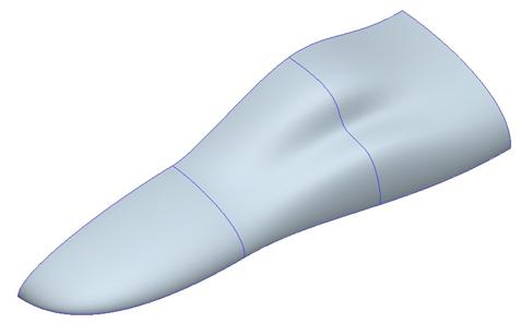
Once selected, click on the middle mouse button to finish selecting internal curves, and our surface will update as shown at the top of the next page.
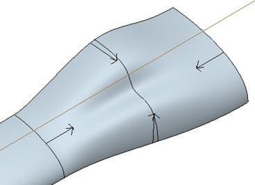
We can see that there is no connection arrow going across the internal boundary curve. This is because there is no surface boundary. The surface is tangent and shares the same curvature across the internal curves. Click on the middle mouse button to finish this surface.
We will now click on the connect surfaces icon once again (![]() ), select the two
surfaces using the Ctrl key, and then change the connection arrows as we
did before to get the following.
), select the two
surfaces using the Ctrl key, and then change the connection arrows as we
did before to get the following.
Click on the middle mouse button to finish the surface connection, and then the blue check mark to complete the style feature. Save the model which looks like the figure at the top of the next page.

There are some rules to using internal surface curves. They are explained in this next section.
Rule 1: Internal curves are not permitted to cross adjacent boundaries.
Rule 2: If two internal curves cross the same borders, they cannot intersect within the surface.
Rule 3: The internal curve must intersect both borders of the surface.
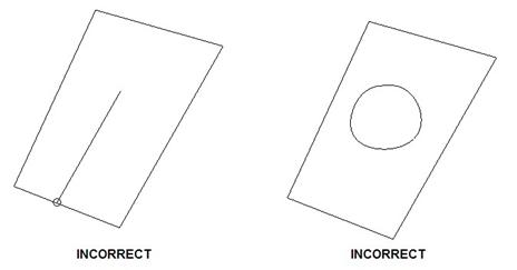
Rule 4: An internal curve cannot intersect the surface boundary at more than two points.
LESSON SUMMARY
In Style, you can create three or four-sided surfaces. You are encouraged to use four-sided surfaces as much as possible and only use three-sided surfaces when defining internal curves or breaking up the three sides into multiple four-sided areas is very difficult to do.
When two surfaces touch each other on a common boundary curve, you can affect the connection condition. A condition of G2 (Curvature) is the smoothest and cleanest connection you can have, but at a minimum, you should always have a G1 (Tangent) condition.
Use internal curves where possible instead of breaking up a single surface into multiple surfaces. This will allow you to create less surfaces and ensure G2 connections across the internal curves.
EXERCISE
Transition.prt
Open up the Transition.prt part file that we created in Lesson 4, and create two surfaces out of the curves that we created, as shown meshed below.
Edit the definition of the existing style feature to add these surfaces. Save the model once you are done.
Basic_Surf.prt
Open up the Basic_Surf.prt part file. It will initially look like the following.
Edit the definition of the style feature, and create two surfaces. Each surface will have four boundary curves and one internal curve. The end result will be the following.
Save and close this model once you are done.