Lesson 3

Lesson Objective: In this lesson, we will learn about the Active plane, both how to use it and how to create it, as well as some of the preferences for the grid on the plane.
USAGE OF ACTIVE PLANES
Whenever you create a style feature, there is always an active plane, even if the grid lines are not visible. There can only be one active plane in the style feature at any given time.
You can, however, specify where your active plane is, and switch it to other locations during the creation of style entities.
When creating style curves, the Planar option places the curve on the active plane. It ensures that all points along that curve are on the same plane.
SELECTING AN ACTIVE PLANE
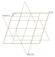
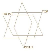
By default, when you first go into a style feature, the active plane is located on the TOP datum plane, as shown below.
To switch the active plane to a different datum plane, click on the following icon in the style toolbar.
![]()
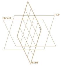
Pick on the datum plane (RIGHT for example) where you want the active plane, and it will now appear on that plane, as shown in the following figure.
CREATING AN ACTIVE PLANE
If you do not have an existing plane from which to select an active plane, you will need to create one. There are two methods for creating datum planes on the fly while in the style feature. If you use the regular datum plane creation tool, you will get a plane that becomes grouped with the style feature in the model tree. This plane is automatically hidden, but can be available for other features to use downstream.
The second method is to create one using a special style tool. If you click on the active plane fly-out icon in the style toolbar, you will see another icon, as shown below.
![]()
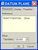
When you click on this icon, you will enter into create datum plane mode. This is the functionality that you use to create regular datum planes. For example, suppose you want to create an active plane that sits 100 inches off of the RIGHT datum plane, you would first click on the icon above, and then select the RIGHT datum plane.
We would see the preview for creating the plane, shown below.
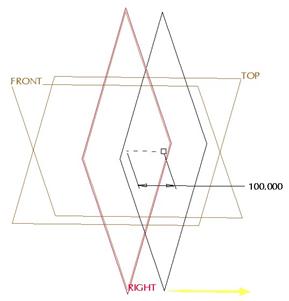
The datum plane creation window looks exactly the same as the regular one you use outside of the style feature.
When you click on OK to complete this datum plane, the active plane will automatically use this plane, as we can see below.
The biggest difference between creating a datum plane this way versus creating one using the regular create datum tool is how it reports in the model tree, and when you can use it.
In the model tree, a datum plane created with the standard tool appears as another feature in the tree, grouped with the style feature, and hidden. It can be used for other non-style features as well as the style feature itself.
A datum plane created using the style feature plane creation icon gets absorbed into that feature, and can only be accessed in that particular style feature. When you finish out of the style feature, it does not appear in the model tree – not even as part of a group like a “make datum” does.
If you were to create a new style feature, the datum plane that we created in the last style feature is not available to use again. So, what is the advantage of the ability to create planes in style mode using this method?
As we mentioned in the last lesson, it is to your advantage to create many different style curves and surfaces in a single style feature. To do this, however, it might require a large number of active planes. You may not wish to have all of these active planes visible in the model tree, therefore you would use this tool to create one that is specifically needed for this style feature only.
ACTIVE PLANE GRID DISPLAY
Even though there is always an active plane in your style feature, you can choose to turn on or off the visibility of the grid for this active plane.
To do this, go to Styling, Preferences from the menu bar. This brings up the window shown at the top of the next page.
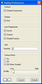
This window is broken up into different functions. These are:
· Surface
· Display
· Auto Regenerate
· Grid
· Surface Mesh
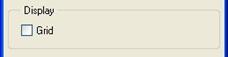
Under the Display function, we can see a box entitled Grid. To turn off the display of the grid, uncheck this box, as shown below.
This will make the grid lines on the active plane disappear from the model, as we can see in the figure below.
Since it is easier to identify the location of the active plane with the grid on, I recommend only turning it off if sketching curves is difficult to do with the grid visible. Therefore we will leave it on, and it comes on again by default when a new session of Pro/ENGINEER is started.
NOTE: If you turn off the grid for one style feature, it is off for all style features until you either 1) turn it back on again, or 2) exit and re-enter Pro/ENGINEER altogether.
ACTIVE PLANE GRID SPACING
The title of this section is a little misleading. We don’t actually control the dimensional spacing of the grid, such as ¼” spacing, etc.
What we have the ability to control is the total number of grid lines we see. To control this, first we want to make sure we can see our active plane grid using the method described in the last section.
Next, we will return to the styling preferences window using Styling, Preferences from the menu bar to get there.
In the Grid section of this window, we can see the following field (the default value of 5 is shown).
![]()
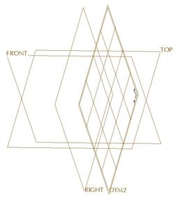
Again, this does not mean that we have a grid spacing of 5 inches or 5 millimeters. It means that we will have a total of 5 grid lines in both the x and y directions in the plane, as shown in the figure below (datum planes have been turned off for better clarity).
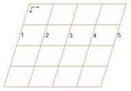
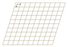
Right now, we have a 4x4 grid pattern. The total number of grid spaces in a given direction is equal to one less than the specified grid spacing. Therefore, to have a 10x10 grid pattern, we would enter a value of 11 in the grid spacing, thereby giving us the following grid.
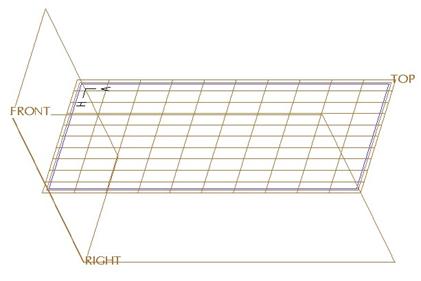
In this example, we have no geometry in our model, therefore our datum planes are squares. If, however, we added geometry, such as a sketched datum curve, that caused the active plane to be a rectangle instead of a square, we would still have the same number of spaces in each direction, however the size of the spacing would be different, as illustrated below for the same grid pattern on a rectangular active plane.
From the example above, we can easily see how we might be able to control the actual spacing itself in terms of our units. If we wanted to have grid spacing of ½”, and we knew the overall size of our model was going to be 10 inches long, we could create a datum curve on the plane we wanted to use as an active plane that was 10 inches in length. Then, when we use this plane for an active plane, we would set the grid spacing to 21, thereby creating 20 equally spaced grids at ½” each in that particular direction.
The catch is that if the model gets larger than the datum curve, the active plane gets larger, and now our spacing is not ½” anymore. Therefore, I would not rely on trying to govern the grid spacing in terms of an actual distance.
ACTIVE PLANE ORIENTATION
When you look at the active plane, you will see a symbol in one of the corners that has a little H and V arrow, as shown below.
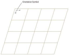
This symbol is used to identify which direction on the plane is considered Horizontal and which direction is considered Vertical. As we get into creating style curves, you will see how this plays a role.
LESSON SUMMARY
There is always an active plane in your style feature. You can select any datum plane to use as an active plane, or create new ones. To ensure the ability to re-use planes as active planes in more than one style feature, you will need to create these planes as stand-alone features.
Leave the grid visible most of the time unless it impedes your ability to see what you are doing. You can also adjust the grid pattern by changing the grid spacing value. You can not directly control the dimensional spacing of the grid, however.
EXERCISE
Create a new part called Active_Plane. Be sure to use a startpart as the template for this part. We want to create an active plane that is exactly 10” by 5” in size, and located 4” away from the TOP datum plane.
We want the grid spacing for the active plane to be ¼” in the small direction (5 inch side).